
Page 69 - Fluid Mechanics and Thermodynamics of Turbomachinery
P. 69
50 Fluid Mechanics, Thermodynamics of Turbomachinery
¾
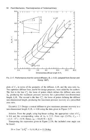
FIG. 2.17. Performance chart for conical diffusers, B 1 D 0.02. (adapted from Sovran and
Klomp 1967).
plots of C p in terms of the geometry of the diffuser, L/R 1 and the area ratio A R .
Two optimum diffuser lines, useful for design purposes, were added by the authors.
Ł
The first is the line C , the locus of points which defines the diffuser area ratio
p
A R , producing the maximum pressure recovery for a prescribed non-dimensional
ŁŁ
length, L/R 1 . The second is the line C , the locus of points defining the diffuser
p
non-dimensional length, producing the maximum pressure recovery at a prescribed
area ratio.
EXAMPLE 2.3. Design a conical diffuser to give maximum pressure recovery in a
non-dimensional length N/R 1 D 4.66 using the data given in Figure 2.17.
Solution. From the graph, using log-linear scaling, the appropriate value of C p
is 0.6 and the corresponding value of A R is 2.13. From eqn. (2.47b), C pi D 1
2
.1/2 Ð 13 / D 0.78. Hence, D D 0.6/0.78 D 0.77.
Transposing the expression given in Figure 2.13b, the included cone angle can
be found:
1
2 D 2 tan f.A 0.5 1//.L/R 1 /gD 11.26 deg.
R