
Page 76 - Fluid Mechanics and Thermodynamics of Turbomachinery
P. 76
Two-dimensional Cascades 57
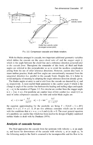
FIG. 3.2. Compressor cascade and blade notation.
With the blades arranged in cascade, two important additional geometric variables
which define the cascade are the space-chord ratio s/l and the stagger angle ,
which is the angle between the chord line and a reference direction perpendicular
to the cascade front. Throughout the remainder of this book, all fluid and blade
angles are referred to this perpendicular so as to avoid the needless complication
arising from the use of other reference directions. However, custom dies hard; in
steam turbine practice, blade and flow angles are conventionally measured from the
tangential direction (i.e. parallel to the cascade front). Despite this, it is better to
avoid ambiguity of meaning by adopting the single reference direction already given.
0
The blades angles at entry to and at exit from the cascade are denoted by ˛ and
1
0
˛ respectively. A most useful blade parameter is the camber angle which is the
2
change in angle of the camber line between the leading and trailing edges and equals
0
˛ 0 ˛ in the notation of Figure 3.2. For circular arc camber lines the stagger angle
1 2
1
0
0
is D .˛ C ˛ /. For parabolic arc camber lines of low camber (i.e. small b/l)as
2 1 2
used in some compressor cascades, the inlet and outlet blade angles are
b/l 0 1 b/l
1
0
˛ D C tan ˛ D tan
2
1
.a/l/ 2 .1 a/l/ 2
the equation approximating for the parabolic arc being Y D XfA.X 1/ C BYg
where X D x/l, Y D y/l. A, B are two arbitrary constants which can be solved
with the conditions that at x D a, y D b and dy/dx D 0. The exact general equation
of a parabolic arc camber line which has been used in the design of highly cambered
turbine blades is dealt with by Dunham (1974).
Analysis of cascade forces
The fluid approaches the cascade from far upstream with velocity c 1 at an angle
˛ 1 and leaves far downstream of the cascade with velocity c 2 at an angle ˛ 2 .In
the following analysis the fluid is assumed to be incompressible and the flow to be