
Page 34 - Fluid Power Engineering
P. 34
Intr oduction to Hydraulic Power Systems 11
Effort Flow Power
Variable Units Variable Units Variable Units
Mech. Force, F N Velocity, v m/s N = Fv W
Linear
Mech. Torque, T Nm Angular rad/s N = ωT W
Rotary speed, ω
Electrical Electric V Electric A N = ei W
(DC) potential, e current, i
3
Hydraulic Pressure, P Pa Flow rate, Q m /s N = PQ W
TABLE 1.2 Effort, Flow, and Power Variables of Different Power Systems
1.6 Exercises
1. State the function of the power systems.
2. Discuss briefly the principle of operation of the different power systems
giving the necessary schemes.
3. Draw the circuit of a simple hydraulic system, in standard symbols, and
explain briefly the function of its basic elements.
4. State the advantages and disadvantages of hydraulic power systems.
5. Draw the circuit of a simple hydraulic system, including a pump, directional
control valves, hydraulic cylinder, relief valve, and pressure gauge. State the
function of the individual elements and discuss in detail the power transmission
and transformation in the hydraulic power systems.
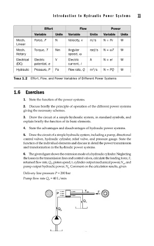
6. The given figure shows the extension mode of a hydraulic cylinder. Neglecting
the losses in the transmission lines and control valves, calculate the loading force, F,
returned flow rate, Q , piston speed, v, cylinder output mechanical power, N , and
T m
pump output hydraulic power, N . Comment on the calculation results, given
h
Delivery line pressure P = 200 bar
Pump flow rate Q = 40 L/min
P