
Page 35 - Fluid Power Engineering
P. 35
12 Cha pte r O n e
Piston diameter D = 100 mm
Piston rod diameter d = 70 mm
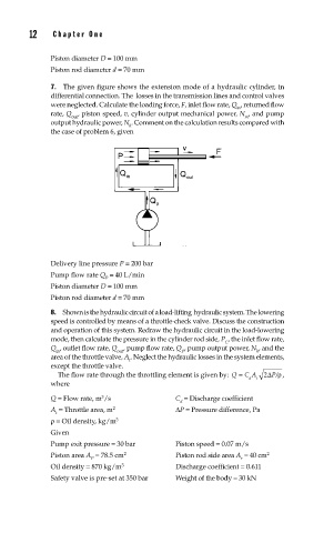
7. The given figure shows the extension mode of a hydraulic cylinder, in
differential connection. The losses in the trans mission lines and control valves
were neglected. Calculate the loading force, F, inlet flow rate, Q , returned flow
in
rate, Q , piston speed, v, cylinder output mechanical power, N , and pump
out m
output hydraulic power, N . Comment on the calculation results compared with
h
the case of problem 6, given
Delivery line pressure P = 200 bar
Pump flow rate Q = 40 L/min
P
Piston diameter D = 100 mm
Piston rod diameter d = 70 mm
8. Shown is the hydraulic circuit of a load-lifting hydraulic system. The lowering
speed is controlled by means of a throttle-check valve. Discuss the construction
and operation of this system. Redraw the hydraulic circuit in the load-lowering
mode, then calculate the pressure in the cylinder rod side, P , the inlet flow rate,
C
Q , outlet flow rate, Q , pump flow rate, Q , pump output power, N , and the
in out P h
area of the throttle valve, A . Neglect the hydraulic losses in the system elements,
t
except the throttle valve.
The flow rate through the throttling element is given by: Q = C A 2Δ P/ρ ,
d t
where
3
Q = Flow rate, m /s C = Discharge coefficient
d
A = Throttle area, m 2 ΔP = Pressure difference, Pa
t
ρ= Oil density, kg/m 3
Given
Pump exit pressure = 30 bar Piston speed = 0.07 m/s
2
Piston area A = 78.5 cm Piston rod side area A = 40 cm 2
P r
Oil density = 870 kg/m 3 Discharge coefficient = 0.611
Safety valve is pre-set at 350 bar Weight of the body = 30 kN