
Page 43 - Fluid Power Engineering
P. 43
20 Cha pte r T w o
The following expression for the pressure losses ΔP was obtained by
substituting Eqs. (2.5) to (2.7) in Eq. (2.4):
128μ L
ΔP = Q = RQ (2.8)
π D 4
The term R expresses the resistance of the hydraulic transmission
line. Its effect is equivalent to that of the electric resistance. Both of them
dissipate energy and both are described by the same mathematical
relation (e = Ri). The power loss ΔN in the pipeline is given by
128μ L
ΔN = QP − QP = Q ΔP = RQ = Q 2 (2.9)
2
1 2 π D 4
Resistance to Fluid Flow in Narrow Conduits
Internal Leakage in Hydraulic Elements Hydraulic power systems
operate at pressure levels up to 700 bar. The internal leakage in hydrau-
lic elements is one of the problems resulting from the operation at high-
pressure levels and the increased clearances due to wear.
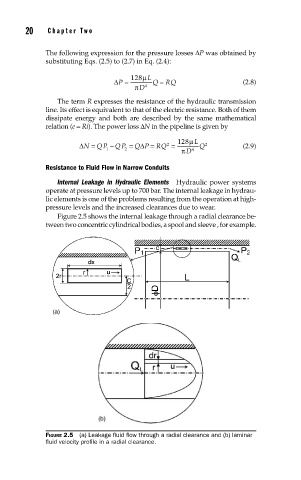
Figure 2.5 shows the internal leakage through a radial clearance be-
tween two concentric cylindrical bodies, a spool and sleeve , for example.
FIGURE 2.5 (a) Leakage fl uid fl ow through a radial clearance and (b) laminar
fl uid velocity profi le in a radial clearance.