
Page 171 - Fluid-Structure Interactions Slender Structure and Axial Flow (Volume 1)
P. 171
PIPES CONVEYING FLUID: LINEAR DYNAMICS I 153
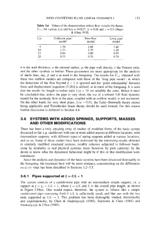
Table 3.6 Values of the dimensionless critical flow velocity for flutter,
-
U,,, for various Lla and hla = 0.0227, I*. = 0.06 and v = 0.5 (Shayo
& Ellen 1978).
Lln ‘Collector pipe’ ‘Free-flow ’ ‘Long pipe’
model model model
5 1.70 1.66 1.40
10 1.23 1.25 1.20
15 0.94 0.96 0.93
20 0.75 0.76 0.74
h is the wall thickness, a the internal radius, ps the pipe wall density, u the Poisson ratio,
and the other symbols as before. These parameters are more appropriate for the analysis
of shells than, say, and u as used in the foregoing. The results for uc, obtained with
these two outflow models are compared with those of the ‘long pipe model’, in which
the behaviour of the flow beyond 6 = 1 is ignored and the ‘point relationship’ between
force and displacement [equation (3.28)] is utilized, as in most of the foregoing. It is seen
that the results for length-to-radius ratio L/a > 10 are sensibly the same. Hence it must
be concluded that, unless the pipe is very short, the use of a refined 3-D fluid dynamic
model for the unsteady flow in the pipe, coupled with an outflow model, is not warranted.
On the other hand, for very short pipes, L/a - 6(5), the Euler-Bernoulli theory ceases
being applicable and Timoshenko beam theory should be used instead. For this reason
further discussion is deferred to Section 4.4.
3.6 SYSTEMS WITH ADDED SPRINGS, SUPPORTS, MASSES
AND OTHER MODIFICATIONS
There has been a truly amazing array of studies of modified forms of the basic system
discussed so far: e.g. cantilevers with one or more added masses at different locations, with
intermediate supports, with different types of spring supports added at various locations,
and so on. Some of these studies have been motivated by the interesting results obtained
in similarly modified structural systems, notably columns subjected to follower loads;
some by similarity to real physical systems; most, however, by pure curiosity: by the
desire to know what the dynamical behaviour might be if this or that modification were
introduced.
Since the analysis and dynamics of the basic systems have been discussed thoroughly in
the foregoing, the treatment here will be more compact, concentrating on the differences
vis-&vis what has been described in Sections 3.2-3.5.
3.6.1 Pipes supported at e = //L < 1
The system consists of a cantilevered pipe with an intermediate simple support, i.e. a
support at 6 = ts = l/L < 1, where 6 = x/L and L is the overall pipe length, as shown
in Figure 3.58(a). One would expect, therefore, the system to Sehave like a simple
cantilevered pipe conveying fluid if E/L is sufficiently small, and like one with the two
ends supported as 1 /L + 1. This problem has been thoroughly studied, theoretically
and experimentally, by Chen & Jendrzejczyk (1983, Edelstein & Chen (1985) and
Jendrzejczyk & Chen (1985).