
Page 216 - Fluid-Structure Interactions Slender Structure and Axial Flow (Volume 1)
P. 216
198 SLENDER STRUCTURES AND AXIAL FLOW
5
t
,
\ I
, I 1
\ , I I
,
\ I I I
\ I
\ I
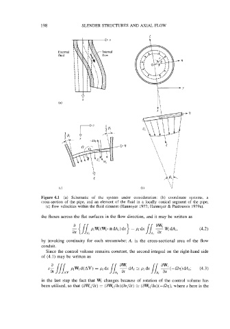
Figure 4.1 (a) Schematic of the system under consideration: (b) coordinate systems, a
cross-section of the pipe, and an element of the fluid in a locally conical segment of the pipe;
(c) flow velocities within the fluid element (Hannoyer 1977; Hannoyer & Pai'doussis 1979a).
the fluxes across the flat surfaces in the flow direction, and it may be written as
(4.2)
by invoking continuity for each streamtube; Ai is the cross-sectional area of the flow
conduit.
Since the control volume remains constant, the second integral on the right-hand side
of (4.1) may be written as
in the last step the fact that Wi changes because of rotation of the control volume has
been utilized, so that (8WJat) = (aWj/as)(~~/ar) = (aWi/ax)(-S2q), where s here is the