
Page 212 - Fluid-Structure Interactions Slender Structure and Axial Flow (Volume 1)
P. 212
194 SLENDER STRUCTURES AND AXIAL FLOW
In all the experiments, the system was made of metal tubes interconnected by short
rubber-pipe segments as in the foregoing, and it was suspended in a horizontal plane,
much as in Figure 3.44. The design of the joints was much refined, however, and this
is partly responsible for the excellent agreement with theory that has been achieved by
Sugiyama and his colleagues.
A great deal of high-quality, interesting theoretical and experimental results have
been obtained in all of this work, mostly anticipating those of the continuous system
(Section 3.6). For that reason, it has been discussed here extremely briefly, but the inter-
ested reader is encouraged to refer to the original papers.
3.8.4 Spatial systems
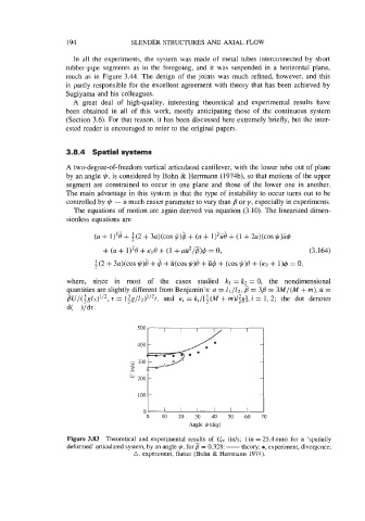
A two-degree-of-freedom vertical articulated cantilever, with the lower tube out of plane
by an angle +, is considered by Bohn & Henmann (1974b), so that motions of the upper
segment are constrained to occur in one plane and those of the lower one in another.
The main advantage in this system is that the type of instability to occur turns out to be
controlled by + - a much easier parameter to vary than #l or y, especially in experiments.
The equations of motion are again derived via equation (3.10). The linearized dimen-
sionless equations are
where, since in most of the cases studied kl = k2 = 0, the nondimensional
quantities are slightly different from Benjamin’s: a = Z1/1~, = 38 = 3M/(M + m), ii =
-
BU/(ig12)1’2, 5 = (ig/12)1/2t, and ~i = ki/[i(M + rn)l;g], i = 1,2; the dot denotes
d( )/dt.
500
400
100
0
0 10 20 30 40 50 60 70
Angle +((leg)
Figure 3.83 Theoretical and experimental results of U,, (ids; 1 in = 25.4 mm) for a ‘spatially
deformed’ articulated system, by an angle y!r, for 3 = 0.328: - theory; 0, experiment, divergence;
A, experiment, flutter (Bohn & Hemnann 1974).