
Page 211 - Fluid-Structure Interactions Slender Structure and Axial Flow (Volume 1)
P. 211
PIPES CONVEYING FLUID: LINEAR DYNAMICS I 193
follows: p = m,/[(m + M)1] and 6 = la/l, where ma is the added mass and 1, its location,
measured from the beginning of the second segment of the system; u = (Ml/k)'l2U.
The effect of an added spring-mass combination at a variable location in the second
segment of the system is studied by Sugiyama (1984). Typical results are shown in
Figure 3.81(b); u, p and 6 are as just defined, while K = K12/k, K being the added spring
stiffness, while k is the stiffness of the articulation joints. As seen in the figure, the system
is generally subject to flutter for small K and to divergence for higher K (cf. Figures 3.64
and 3.65).
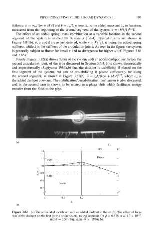
Finally, Figure 3.82(a) shows flutter of the system with an added dashpot, just before the
second articulation joint, of the type discussed in Section 3.6.4. It is shown theoretically
and experimentally (Sugiyama 1986a,b) that the dashpot is stabilizing if placed on the
first segment of the system, but can be destabilizing if placed sufficiently far along
the second segment, as shown in Figure 3.82(b); = c,l/[k(m +M)Z]'/2, where c, is
the added dashpot constant. The stabilizatioddestabilization mechanism is also discussed,
and in the second case is shown to be related to a phase shift which facilitates energy
transfer from the fluid to the pipe.
0 0.5 1 .o
51
(b)
Figure 3.82 (a) The articulated cantilever with an added dashpot in flutter. (b) The effect of loca-
tion of the dashpot on the first (at cl) or the second (at (2) segment, for /3 = 0.575, c = 1.7 x
and = 0.59 (Sugiyama et al. 1986a,b).