
Page 222 - Fluid-Structure Interactions Slender Structure and Axial Flow (Volume 1)
P. 222
204 SLENDER STRUCTURES AND AXIAL FLOW
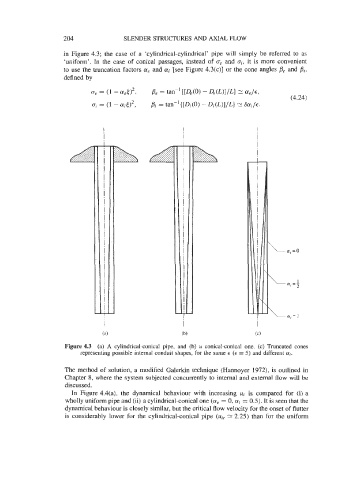
in Figure 4.3; the case of a ‘cylindrical-cylindrical’ pipe will simply be referred to as
‘uniform’. In the case of conical passages, instead of 0, and oi, it is more convenient
to use the truncation factors (Ye and ai [see Figure 4.3(c)] or the cone angles Be and Pi,
a; = 0
\
ff, =;
\
I
Figure 4.3 (a) A cylindrical-conical pipe, and (b) a conical-conical one. (c) Truncated cones
representing possible internal conduit shapes, for the same E (6 = 5) and different a;.
The method of solution, a modified Galerkin technique (Hannoyer 1972), is outlined in
Chapter 8, where the system subjected concurrently to internal and external flow will be
discussed.
In Figure 4.4(a), the dynamical behaviour with increasing u; is compared for (i) a
wholly uniform pipe and (ii) a cylindrical-conical one (a, = 0, a; = 0.5). It is seen that the
dynamical behaviour is closely similar, but the critical flow velocity for the onset of flutter
is considerably lower for the cylindrical-conical pipe (uic 2: 2.25) than for the uniform