
Page 226 - Fluid-Structure Interactions Slender Structure and Axial Flow (Volume 1)
P. 226
208 SLENDER STRUCTURES AND AXIAL FLOW
ffi
0.0 0.1 0.2 0.3 0.4 0.5 0.6 0.7
I I I I I I I I
ffe
0.0 0.1 0.2 0.3 0.4 0.5 0.6
\.
6- , I I I I 1
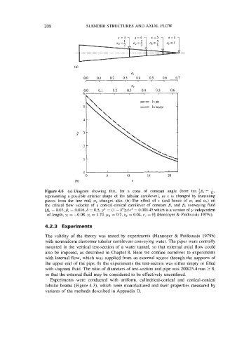
-.- In air
In
- water
2-
1-
Figure 4.6 (a) Diagram showing that, for a cone of constant angle (here tan ;Be =,A,
representing a possible exterior shape of the tubular cantilever), as E is changed by truncating
pieces from the free end, a, changes also. (b) The effect of E (and hence of ai and a,) on
the critical flow velocity of a conical-conical cantilever of constant Bi and Be conveying fluid
[Be = 0.03, Pi = 0.016, S = 0.5, y* = (1 - S4)y/c3 = 0.001 45 which is a version of y independent
of length, yi = -0.08, ye = 1.70, ,%d = 0.2, ud = 0.04, c, = 01 (Hannoyer & Paidoussis 1979a).
4.2.3 Experiments
The validity of the theory was tested by experiments (Hannoyer & PaYdoussis 1979b)
with nonuniform elastomer tubular cantilevers conveying water. The pipes were centrally
mounted in the vertical test-section of a water tunnel, so that external axial flow could
also be imposed, as described in Chapter 8. Here we confine ourselves to experiments
with internal flow, which was supplied from an external source through the supports of
the upper end of the pipe. In the experiments the test-section was either empty or filled
with stagnant fluid. The ratio of diameters of test-section and pipe was 200125.4 mm 2 8,
so that the external fluid may be considered to be effectively unconfined.
Experiments were conducted with uniform, cylindrical-conical and conical-conical
tubular beams (Figure 4.3), which were manufactured and their properties measured by
variants of the methods described in Appendix D.