
Page 228 - Fluid-Structure Interactions Slender Structure and Axial Flow (Volume 1)
P. 228
210 SLENDER STRUCTURES AND AXIAL FLOW
8
6
0 >
2
rn
I I I
i
20 - i
i
V
V
- V
10
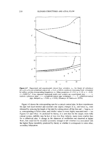
Figure 4.7 Theoretical and experimental critical flow velocities, uicr for flutter of cylindrical
(Be = /?i = 0) and cylindrical-conical (Be = 0, = 0.014) cantilevers conveying fluid, surrounded
by still air; and the corresponding frequencies, w,. Other parameters: S = 0.5, ye = 1.0, yj = -0.03,
y = 0.00251~~. Lines represent theoretical results and symbols are experimental data: -.- , 0,
uniform cylindrical pipe; -, cylindrical-conical pipe, undamped; - - -, V, cylindrical-conical
pipe, damped (pd = 0.08, vd = 0.02); (Hannoyer & Paidoussis 1979b).
Figure 4.9 shows the corresponding case for a conical-conical pipe. In these experiments
the pipe had fixed internal and external cone angles; changes in ai, and hence a,, were
obtained by reducing the length of the pipe by cutting pieces off the free end - large u, or
a; corresponding to fuller cones, and smaller values to more highly truncated ones - see
Figures 4.3 and 4.6(a). As predicted by theory, it is seen that for the longer, more fully
conical system, stability may be lost at very low flow velocity, many times smaller than
for a cylindrical pipe. A change in the character of oscillation was observed at higher
flows, but could not be recorded accurately enough to tell whether it is associated with
the higher flutter instability predicted by theory or whether it corresponds to some other,
secondary bifurcation.