
Page 369 - Fluid-Structure Interactions Slender Structure and Axial Flow (Volume 1)
P. 369
PIPES CONVEYING FLUID: NONLINEAR AND CHAOTIC DYNAMICS 349
show that the interpretation of the dynamics is very sensitive, in a way that nonchaotic
dynamics can never be, particularly when judging the success or otherwise of analytical
modelling. This will become evident in the course of the presentation, and is discussed
in the two paragraphs preceding the last two of this section.
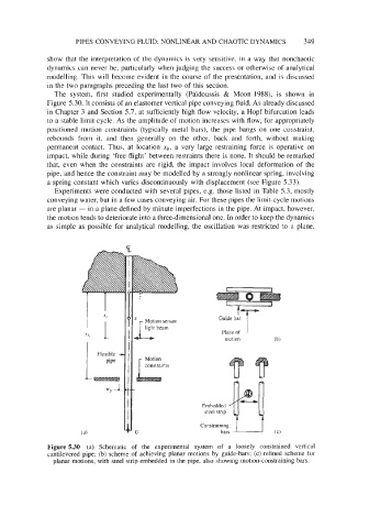
The system, first studied experimentally (Paidoussis & Moon 1988), is shown in
Figure 5.30. It consists of an elastomer vertical pipe conveying fluid. As already discussed
in Chapter 3 and Section 5.7, at sufficiently high flow velocity, a Hopf bifurcation leads
to a stable limit cycle. As the amplitude of motion increases with flow, for appropriately
positioned motion constraints (typically metal bars), the pipe bangs on one constraint,
rebounds from it, and then generally on the other, back and forth, without making
permanent contact. Thus, at location Xb, a very large restraining force is operative on
impact, while during ‘free flight’ between restraints there is none. It should be remarked
that, even when the constraints are rigid, the impact involves local deformation of the
pipe, and hence the constraint may be modelled by a strongly nonlinear spring, involving
a spring constant which varies discontinuously with displacement (see Figure 5.33).
Experiments were conducted with several pipes, e.g. those listed in Table 5.3, mostly
conveying water, but in a few cases conveying air. For these pipes the limit-cycle motions
are planar - in a plane defined by minute imperfections in the pipe. At impact, however,
the motion tends to deteriorate into a three-dimensional one. In order to keep the dynamics
as simple as possible for analytical modelling, the oscillation was restricted to a plane,
Motion sensor
light beam
Embedded
steel strip
Constraining
bars
Figure 5.30 (a) Schematic of the experimental system of a loosely constrained vertical
cahevered pipe; (b) scheme of achieving planar motions by guide-bars;-(c) refined scheme for
planar motions, with steel strip embedded in the pipe, also showing motion-constraining bars.