Page 447 - Fluid-Structure Interactions Slender Structure and Axial Flow (Volume 1)
P. 447
CURVED PIPES CONVEYING FLUID                     419

              around the  centreline; the  angle of  rotation  is  denoted here by  @  and,  since 8 is  here
              assumed to be  small (small deformation assumption), $ =  + 7. Hence, the deformed
              state of the pipe is determined by the generalized coordinates u, v, w and $.
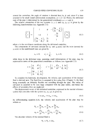
                The  relative orientation of  the  two  systems  (x, y, z) and  (xo, yo, 20)  is  given  by  the
              following transformation (see Appendix J. 1):


              where s is the curvilinear coordinate along the deformed centreline.
                The components of  curvature (around the XO- and  yo-axes) and the twist (around the
              zo-axis) in the undeformed state are given by


                                                                                    (6.2)

              while  those  in  the  deformed  state,  assuming  small deformations of  the  pipe,  may  be
              expressed in terms of  the generalized coordinates as follows (see Appendix J.2):


                 To  complete the kinematic development, the velocity  and acceleration of  the internal
              fluid is derived next. The fluid flow is assumed to be a plug flow (Chapter 3), the fluid
              being  essentially  an  infinitely  flexible rod  travelling  through  the  pipe.  The  radius  of
              curvature  is  assumed  to  be  very  large compared  with  the  pipe  radius,  and  hence  the
              effects of secondary flow are neglected.
                 The displacement vector of the deformed centreline, expressed in the inertial reference
               system that coincides with the system (xg, yo, ZO),  is given by

                                         r = ue,,  +we,  +we,,.                     (6.4)
              By  differentiating  equation (6.4), the  velocity  and  acceleration  of  the  pipe  may  be
              written as
                                          au      av      aw
                                     V  - -e,,  + - ey0 + -e,,
                                      y-  at      at      at
                                          aZu      aZv     a2w
                                     ap = - ex0 + -e     + -e,.
                                           at2     at2  yo   at2
                 The absolute velocity of the internal fluid is

