
Page 126 - Fluid mechanics, heat transfer, and mass transfer
P. 126
104 PUMPS, EJECTORS, BLOWERS, AND COMPRESSORS
. How are impellers classified?
& Based on major direction of flow in reference to the
axis of rotation, impellers are classified as follows:
➢ Radial flow impellers.
➢ Axial flow impellers.
➢ Mixed flow impellers.
- Based on suction type, impellers are classified as
follows:
➢ Single suction: Liquid inlet on one side.
➢ Double suction: Liquid inlet to the impeller sym-
metrically from both sides.
- Based on mechanical construction, impellers are
classified as follows:
➢ Open: No shrouds or wall to enclose the vanes.
➢ Semiopen type or vortex type.
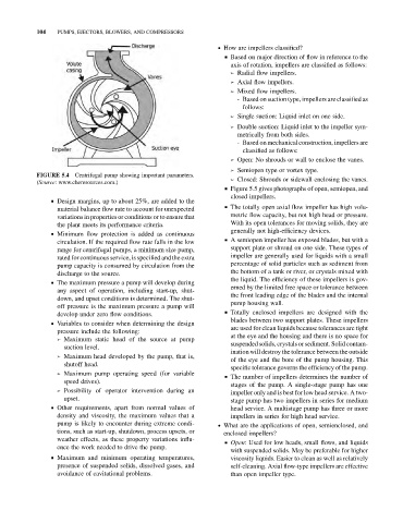
FIGURE 5.4 Centrifugal pump showing important parameters.
➢ Closed: Shrouds or sidewall enclosing the vanes.
(Source: www.cheresources.com.)
& Figure 5.5 gives photographs of open, semiopen, and
closed impellers.
& Design margins, up to about 25%, are added to the
& The totally open axial flow impeller has high volu-
material balance flow rate to account for unexpected
variations in properties or conditions or to ensure that metric flow capacity, but not high head or pressure.
the plant meets its performance criteria. With its open tolerances for moving solids, they are
generally not high-efficiency devices.
& Minimum flow protection is added as continuous
& A semiopen impeller has exposed blades, but with a
circulation. If the required flow rate falls in the low
range for centrifugal pumps, a minimum size pump, support plate or shroud on one side. These types of
rated for continuous service, is specified and the extra impeller are generally used for liquids with a small
percentage of solid particles such as sediment from
pump capacity is consumed by circulation from the
discharge to the source. the bottom of a tank or river, or crystals mixed with
the liquid. The efficiency of these impellers is gov-
& The maximum pressure a pump will develop during
erned by the limited free space or tolerance between
any aspect of operation, including start-up, shut-
the front leading edge of the blades and the internal
down, and upset conditions is determined. The shut-
pump housing wall.
off pressure is the maximum pressure a pump will
& Totally enclosed impellers are designed with the
develop under zero flow conditions.
blades between two support plates. These impellers
& Variables to consider when determining the design
are used for clean liquids because tolerances are tight
pressure include the following:
at the eye and the housing and there is no space for
➢ Maximum static head of the source at pump
suspended solids, crystals or sediment. Solid contam-
suction level.
ination will destroy the tolerance between the outside
➢ Maximum head developed by the pump, that is,
of the eye and the bore of the pump housing. This
shutoff head.
specific tolerance governs the efficiency of the pump.
➢ Maximum pump operating speed (for variable
& The number of impellers determines the number of
speed drives).
stages of the pump. A single-stage pump has one
➢ Possibility of operator intervention during an
impeller only and is best for low head service. A two-
upset. stage pump has two impellers in series for medium
& Other requirements, apart from normal values of head service. A multistage pump has three or more
density and viscosity, the maximum values that a impellers in series for high head service.
pump is likely to encounter during extreme condi- . What are the applications of open, semienclosed, and
tions, such as start-up, shutdown, process upsets, or enclosed impellers?
weather effects, as these property variations influ-
& Open: Used for low heads, small flows, and liquids
ence the work needed to drive the pump.
with suspended solids. May be preferable for higher
& Maximum and minimum operating temperatures, viscosity liquids. Easier to clean as well as relatively
presence of suspended solids, dissolved gases, and self-cleaning. Axial flow-type impellers are effective
avoidance of cavitational problems. than open impeller type.