
Page 146 - Fluid mechanics, heat transfer, and mass transfer
P. 146
124 PUMPS, EJECTORS, BLOWERS, AND COMPRESSORS
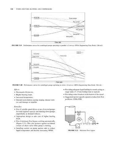
FIGURE 5.19 Performance curves for centrifugal pumps operating in parallel. (Courtesy: GPSA Engineering Data Book, 12th ed.)
FIGURE 5.20 Performance curves for centrifugal pumps operating in series. (Courtesy: GPSA Engineering Data Book, 12th ed.)
Effects & Providing adequate liquid holdup in vessels acting as
& Decreased efficiencies. surge tanks (5–15 min holdup time is typical).
& Higher bearing loads. & Providing vortex breakers in the bottom of the vessel.
& Increased temperature. & Suggested suction-specific speeds to reduce low-flow
problems: 8500–9500.
& Internal recirculation causing surging, intense vorti-
ces and damage to impeller.
Remedies
& Use of variable speed drives or use of several pumps
for total required capacity and shutting down pumps
sequentially as demand reduces.
& Appropriate design to take care of higher bearing
loads.
& Use of minimum flow bypass working automatically
(Figure 5.21). This also protects against accidental
closure of check valve while pump is running.
& Installing coolers on pump suction side to reduce
liquid temperature and thereby increasing NPSH. FIGURE 5.21 Minimum flow bypass.