
Page 182 - Fluid mechanics, heat transfer, and mass transfer
P. 182
160 PUMPS, EJECTORS, BLOWERS, AND COMPRESSORS
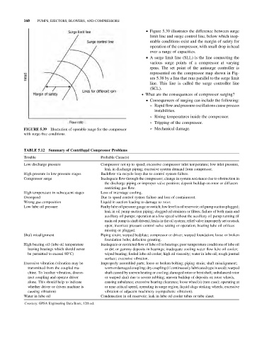
& Figure 5.39 illustrates the difference between surge
limit line and surge control line, below which inop-
erable conditions exist and the margin of safety for
operation of the compressor, with small drop in head
over a range of capacities.
& A surge limit line (SLL) is the line connecting the
various surge points of a compressor at varying
rpms. The set point of the antisurge controller is
represented on the compressor map shown in Fig-
ure 5.38 by a line that runs parallel to the surge limit
line. This line is called the surge controller line
(SCL).
. What are the consequences of compressor surging?
& Consequences of surging can include the following:
➢ Rapid flow and pressure oscillations cause process
instabilities.
➢ Rising temperatures inside the compressor.
➢ Tripping of the compressor.
FIGURE 5.39 Illustration of operable range for the compressor ➢ Mechanical damage.
with surge-free conditions.
TABLE 5.12 Summary of Centrifugal Compressor Problems
Trouble Probable Cause(s)
Low discharge pressure Compressor not up to speed; excessive compressor inlet temperature; low inlet pressure,
leak in discharge piping; excessive system demand from compressor.
High pressure in low pressure stages Backflow via recycle loop due to control system failure.
Compressor surge Inadequate flow through the compressor; change in system resistance due to obstruction in
the discharge piping or improper valve position; deposit buildup on rotor or diffusers
restricting gas flow.
High temperature in subsequent stages Loss of interstage cooling.
Overspeed Due to speed control system failure and loss of containment.
Wrong gas composition Liquid in suction leading to damage to rotor.
Low lube oil pressure Faulty lube oil pressure gauge or switch; low level in oil reservoir;oil pump suction plugged;
leak in oil pump suction piping; clogged oil strainers or filters; failure of both main and
auxiliary oil pumps; operation at a low speed without the auxiliary oil pump running (if
main oil pump is shaft driven); leaks in the oil system; relief valve improperly set or stuck
open; incorrect pressure control valve setting or operation; bearing lube oil orifices
missing or plugged.
Shaft misalignment Piping strain; warped bedplate; compressor or driver; warped foundation; loose or broken
foundation bolts; defective grouting.
High bearing oil (lube oil temperature Inadequate or restricted flow of lube oil to bearings; poor temperature conditions of lube oil
leaving bearings which should never or dirt or gummy deposits in bearings; inadequate cooling water flow lube oil cooler;
be permitted to exceed 80 C) wiped bearing; fouled lube oil cooler; high oil viscosity; water in lube oil; rough journal
surface; excessive vibration.
Excessive vibration (vibration may be Improperly assembled parts; loose or broken bolting; piping strain; shaft misalignment;
transmitted from the coupled ma- worn or damaged coupling; dry coupling (if continuously lubricated type is used); warped
chine. To localize vibration, discon- shaft caused by uneven heating or cooling; damaged rotor or bent shaft; unbalanced rotor
nect coupling and operate driver or warped shaft due to severe rubbing; uneven buildup of deposits on rotor wheels,
alone. This should help to indicate causing unbalance; excessive bearing clearance; loose wheel(s) (rare case); operating at
whether driver or driven machine is or near critical speed, operating in surge region; liquid slugs striking wheels; excessive
causing vibration) vibration of adjacent machinery (sympathetic vibration).
Water in lube oil Condensation in oil reservoir; leak in lube oil cooler tubes or tube sheet.
Courtesy: GPSA Engineering Data Book, 12th ed.