
Page 236 - Fluid mechanics, heat transfer, and mass transfer
P. 236
214 TWO-PHASE FLOW SYSTEMS
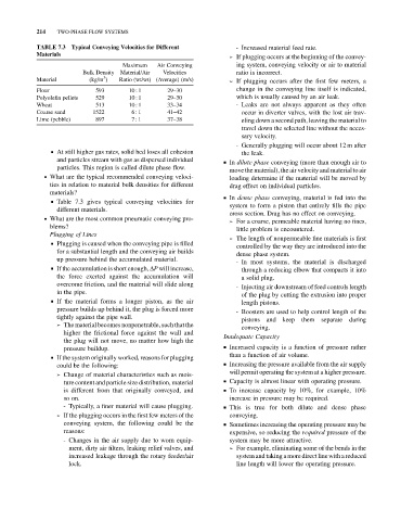
TABLE 7.3 Typical Conveying Velocities for Different - Increased material feed rate.
Materials
➢ If plugging occurs at the beginning of the convey-
Maximum Air Conveying ing system, conveying velocity or air to material
Bulk Density Material/Air Velocities ratio is incorrect.
3
Material (kg/m ) Ratio (wt/wt) (Average) (m/s) ➢ If plugging occurs after the first few meters, a
Flour 593 10 : 1 29–30 change in the conveying line itself is indicated,
Polyolefin pellets 529 10 : 1 29–30 which is usually caused by an air leak.
Wheat 513 10 : 1 33–34 - Leaks are not always apparent as they often
Coarse sand 1522 6 : 1 41–42 occur in diverter valves, with the lost air trav-
Lime (pebble) 897 7 : 1 37–38 eling down a second path, leaving the material to
travel down the selected line without the neces-
sary velocity.
- Generally plugging will occur about 12 m after
& At still higher gas rates, solid bed loses all cohesion
the leak.
and particles stream with gas as dispersed individual & In dilute phase conveying (more than enough air to
particles. This region is called dilute phase flow.
move the material), the air velocity and material to air
. What are the typical recommended conveying veloci- loading determine if the material will be moved by
ties in relation to material bulk densities for different drag effect on individual particles.
materials?
& In dense phase conveying, material is fed into the
& Table 7.3 gives typical conveying velocities for
system to form a piston that entirely fills the pipe
different materials.
cross section. Drag has no effect on conveying.
. What are the most common pneumatic conveying pro-
➢ For a coarse, permeable material having no fines,
blems? little problem is encountered.
Plugging of Lines
➢ The length of nonpermeable fine materials is first
& Plugging is caused when the conveying pipe is filled
controlled by the way they are introduced into the
for a substantial length and the conveying air builds
dense phase system.
up pressure behind the accumulated material.
- In most systems, the material is discharged
& If the accumulation is short enough, DP will increase,
through a reducing elbow that compacts it into
the force exerted against the accumulation will a solid plug.
overcome friction, and the material will slide along
- Injecting air downstream of feed controls length
in the pipe.
of the plug by cutting the extrusion into proper
& If the material forms a longer piston, as the air
length pistons.
pressure builds up behind it, the plug is forced more
- Boosters are used to help control length of the
tightly against the pipe wall.
pistons and keep them separate during
➢ The material becomes nonpenetrable, such that the
conveying.
higher the frictional force against the wall and
Inadequate Capacity
the plug will not move, no matter how high the
pressure buildup. & Increased capacity is a function of pressure rather
than a function of air volume.
& If the system originally worked, reasons for plugging
could be the following: & Increasing the pressure available from the air supply
will permit operating the system at a higher pressure.
➢ Change of material characteristics such as mois-
ture content and particle size distribution, material & Capacity is almost linear with operating pressure.
is different from that originally conveyed, and & To increase capacity by 10%, for example, 10%
so on. increase in pressure may be required.
- Typically, a finer material will cause plugging. & This is true for both dilute and dense phase
➢ If the plugging occurs in the first few meters of the conveying.
conveying system, the following could be the & Sometimes increasing the operating pressure may be
reasons: expensive, so reducing the required pressure of the
- Changes in the air supply due to worn equip- system may be more attractive.
ment, dirty air filters, leaking relief valves, and ➢ For example, eliminating some of the bends in the
increased leakage through the rotary feeder/air system and taking a more direct linewith a reduced
lock. line length will lower the operating pressure.