
Page 238 - Fluid mechanics, heat transfer, and mass transfer
P. 238
216 TWO-PHASE FLOW SYSTEMS
area helps material to move out of the rotor Material-Related Factors
during the limited time available. & Particle size.
& Separating the feeder from the air lock allows for a & Particle shape.
free space between the two, in which venting can be & Particle strength or modulus or hardness.
accomplished.
& Elasticity of particles.
& In venting by venturi, a small venturi using plant air & Breakage function of material.
from the feeder either aspirates material and air from . What are the principal measures that help reduce wear
the feeder and introduces it into the conveying line or in existing pneumatic conveying systems?
vents it to the top of the bin/silo. & Reducing conveying velocity or increasing the solids
Material Degradation loading ratio.
& Frequently, the material being conveyed has a change
& Reducing the number of bends by simplifying the
in physical characteristics making it unsuitable for
line layout wherever possible.
marketing.
& Replacing bends with designs that are less prone to
➢ Pneumatic conveying can create fines.
attrition.
➢ Altered appearance due to scuffing of the surface,
. What are the commonly used elbows or bends in
which would change the luster of the product.
pneumatic conveying? How are they classified?
& Conveying with as high a loading (solids to air ratio)
& Elbows or bends are classified based on their radius of
as possible and as low a velocity as possible will
curvature and diameter of the conveyor line.
minimize the above problems.
& Elbow: Ratio of radius of curvature R and line size D
➢ Pressure conveying systems are better suited for
in the range of 1–2.5.
this purpose than vacuum conveying systems as
& Short Radius Bend: R/D in the range of 3–7.
the latter involve dilute phase with low solids
content and lower velocities. & Long Radius Bend: R/D in the range of 8–14.
➢ Avoiding cyclones and slowing down the material & Long Sweep Bend: R/D in the range of 15–24.
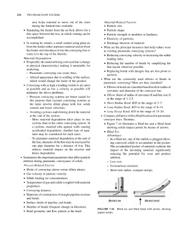
at the end of the system. . Compare a blind teewith a blind bend used in pneumatic
- More material degradation takes place in one conveyor lines. Illustrate.
cyclone than in the entire conveying system. In & Figure 7.16 illustrates a blind tee and a blind bend
a cyclone, material rubs against walls causing showing solids impact points by means of arrows.
accelerated degradation. Another type of sepa- & Blind Tee:
rator may be considered for such cases.
Advantages
- To minimize material degradation at the end of ➢ In a blind tee, one of the outlets is plugged allow-
the line, diameter of the line may be increased by ing conveyed solids to accumulate in the pocket.
one pipe diameter for a distance of 6 m. This The accumulated pocket of material cushions the
reduces material impact on the receiver and impact of the incoming material, significantly
hence degradation. reducing the potential for wear and product
. Summarize the important parameters that affect particle attrition.
attrition during pneumatic conveyance of solids. ➢ Low cost.
Process-Related Factors ➢ Erosion/wear resistant.
& Mode of conveying (dense versus dilute phase). ➢ Short turn radius; compact design.
& Gas velocity or particle velocity.
& Solids loading (or concentration).
& Temperature of gas and solids (coupled with material
properties).
& Conveying distance.
& Materials of construction of straight pipeline sections
and bends.
& Surface finish of pipeline and bends.
& Number of bends (frequent change in direction).
FIGURE 7.16 Blind tee and blind bend with arrows showing
& Bend geometry and flow pattern at the bend.
impact points.