
Page 321 - Fluid mechanics, heat transfer, and mass transfer
P. 321
SHELL AND TUBE HEAT EXCHANGERS
302
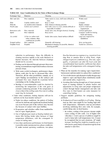
TABLE 10.8 Some Considerations for the Choice of Heat Exchanger Design
Exchanger Type Materials Cleaning Comments
Shell and tube Most materials Tubes easier to clean; shell more difficult to Widely used
clean
Plate Usually stainless steel Easy to clean Compact
Plate-fin Al, stainless steel, titanium Only chemical cleaning possible Highly compact
Double pipe Carbon steel common Inner tube easier to clean; annulus difficult or Used for small area
impossible if welded requirements
Immersion coils Most materials Inside tubes only through chemical cleaning Limited application
Spiral Most materials Easy access Compact; useful for fouling
fluids and slurries
Air-cooled Al fins on carbon steel Inside tubes easier, finned surfaces difficult Large area required for
tubes common, other installation
combinations possible
Scraped surface Most materials Generally self-cleaning Have moving parts
Graphite block Graphite Mechanical cleaning not possible, chemical Useful for corrosives
cleaning possible
reduction in performance. Since the difficulty in flow lies between two regimes (e.g., transition from
cleaning increases rapidly as the scale thickness or slug flow to annular flow to misty flow), slight
deposit increases, the intervals between cleanings changes in process conditions (e.g., flow rate, vapor
should not be excessive. quality, or pressure) can alter the local axial and
& Fouling can be detected through pressure drop mon- circumferential heat transfer coefficient that alters
itoring, as nonuniform rough fouled surfaces increase the tube wall temperatures with consequent fouling
pressure drops. rates.
& With water-cooled exchangers, performance degra- . What are the remedies for making vapor–liquid distri-
dation could also be due to decreased flow rates. bution more uniform under two-phase flow conditions?
Therefore, all the other possibilities, namely, air or & Use of tube inserts and alternative baffle designs may
vapor binding (accumulation) on the surfaces and improve vapor and liquid phase distribution inside
decreased flow rates should be examined before and outside tubes, respectively.
concluding on the fouling process. & Avoiding film boiling through use of lower pressure
& Buildup of noncondensables could be checked by steam as heating medium in tubular heaters and
monitoring the temperature of the vent gases at adjustments in firing rates and proper temperature
constant condensing pressure. If the temperature is control through burner management and tube side
close to that of the cooling water, flow rate of cooling flow rates in fired heaters are some measures for
water may be increased. controlling fouling.
. Under what conditions, fouling deposits will not be . Suggest suitable guidelines for mitigating fouling
uniform on the heat transfer surfaces? problems.
& Under two-phase conditions, the pattern of fouling & Evaluation of Causes andEffects of Fouling: During
will not be uniform and significant localized fouling start-up, flow rates might be low leading high tube
can occur because part of the surfaces may become wall temperatures. Alternative start-up procedures
dry because of contact with vapor bubbles. involving stabilizing flow rates with, for example,
& Evaporators and reboilers suffer from maldistribu- careful firing rates in fired heaters.
tion of vapor–liquid phases. ➢ In coolers, cooling of hot process streams might
& Use of high-pressure steam as heating medium pro- cause scaling of tube walls. Use of higher tube
motes film boiling inside tubes because of large velocities (>2 m/s) and use of additives might be
temperature differences, with the consequent in- used to keep tube wall temperatures low. It must
crease in fouling rates. be recognized that in such situations, DP might
increase. Swirling flow might be created by use of
& Less than satisfactory performance in fired heaters
tube inserts, particularly in transition regions from
is possible under unexpected two-phase conditions.
annular to mist flow.
If, under normal operating conditions, two-phase