
Page 326 - Fluid mechanics, heat transfer, and mass transfer
P. 326
HEAT EXCHANGERS 307
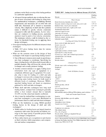
guidance on the likely severity of the fouling problem TABLE 10.9 Fouling Factors for Different Streams (10 m K/W)
4
2
in a particular application.
Fouling
& Advanced design methods aim at reducing the mar- Stream Factor
gin of errors associated with fouling by using itera- Water Streams
tive mathematical techniques, considering thermal Boiler blowdown, brackish, river waters 3.5–5.3
requirements and maximum DP on both tube and Seawater, treated cooling tower water, spray pond water 1.75–3.5
shell side. Maximum DP is related to maximum Distilled water, closed-cycle condensate 0.7–1.75
velocity. The complexity of shell side flow patterns Closed loop treated water, engine jacket water 1.75
makes it difficult to specify velocity constraints Treated boiler feed water 0.9
compared to tube side flow patterns. As low veloc- Industrial Liquid Streams
ities are conducive to fouling process, particular Ammonia (oil bearing) 5.25
Engine lube oil, hydraulic oil, transformer oil, refrigerants 1.75
attention must be paid to low-velocity constraints.
Methanol, ethanol, ethylene glycol 3.5
The minimum velocity could be defined as the ve-
Industrial organic fluids 1.75–3.5
locity for threshold fouling rate in applying these
Cracking and Coking Unit Streams
design techniques.
Heavy cycle oil, light coker gas oil 5.3–7
. Give typical fouling factors for different streams in heat
Bottom slurry oils 5.3
exchangers. Heavy coker gas oil 7–9
& Table 10.9 gives fouling factor data for various Light cycle oil 3.5–5.3
process streams. Light liquid products, overhead vapors 3.5
Light-End Processing Streams
. What are the common errors in the design of heat
Overhead gas, vapor, and overhead liquid products 1.75
exchangers with respect to specifying fouling factors?
Alkylation trace acid streams 3.5
& One of the most common errors made in specifying a Absorber oils 3.5–5.3
new heat exchanger is overdesign. Specifying too Reboiler streams 3–5.5
large a fouling factor will often result in more tube or Chemical Process Streams
parallel channels. This will lower the velocity in the
Solvent vapor, stable overhead products 1.75
exchanger and actually promote fouling.
Natural gas 1.75–3.5
& Another common mistake is to apply fouling factor
Acid gas 3.5–5.3
information from one type of equipment to a Crude Oil Refinery Streams
completely different type of equipment. For exam- 120 C 3.5–7
ple, what is true for fouling of a shell and tube 120–180 C 5.25–7
exchanger is not true with a compact heat exchanger. 180–230 C 7–9
Specifying same fouling factors for both result in >230 C 9–10.5
different levels of overdesign. Moreover, TEMA- Petroleum Streams
specified fouling factors are based on experience LPG 1.75–3
gathered for shell and tube exchangers. Natural gasoline, rich oil 1.75–3.5
Lean oil 3.5
& While shell and tube exchangers have long used
Process Liquid Streams
fouling factors, compact heat exchangers generally Bottom products 1.75–3.5
utilize a heat transfer margin that is typically MEAandDEAsolutions,DEGandTEGsolutions,causticsolutions 3.5
10–25% over the clean heat transfer coefficient. Crude and Vacuum Liquid Streams
& Also it must be realized that overdesigning in com- Gasoline 3.5
pact heat exchangers is even more detrimental to Kerosene, light distillates, gas oil, naphtha 3.5–5.3
performance than in a shell and tube heat exchanger. Heavy fuel oil 5.3–12.3
Atmospheric tower bottoms 12.3
. What are the limitations in using TEMA-specified
Vacuum tower bottoms 17.6
fouling factors in the design of shell and tube
Industrial Gas or Vapor Streams
exchangers?
Compressed air, ammonia 1.75
& TEMA tables for fouling factors are largely based on
Oily exhaust steam 2.6–3.5
experience with water and provide incomplete cov- CO 2 , oily refrigerant 3.5
erage to the large variety of possible process fluids Nonoily steam, natural gas originated flue gas 9
and exchanger configurations. Coal originated flue gas 17.5
& These tables barely give recognition to such factors
Source: Chenoweth JM. Final Report of the HTRI/TEMA Joint Committee
as fluid velocities, bulk temperatures, and composi- to Review the Fouling Section of the TEMA Standards. Heat Transfer
tion and surface temperatures. Engineering 1990;11(1):73–107.