
Page 203 - Fluid-Structure Interactions Slender Structure and Axial Flow (Volume 1)
P. 203
PIPES CONVEYING FLUID: LINEAR DYNAMICS I 185
Benjamin (1961b) conducted a set of model experiments with articulated pipes made up
of segments of brass or glass tubes (typically 12.7 mm in diameter, 0.20-0.62 m long),
interconnected by joints made of short lengths of rubber tubing bound to the rigid tubes
securely with wire. Care was taken to relieve stresses at the joints and to ensure a smooth
flow passage from tube to joint and on to the next tube. Some experiments were conducted
with kl = k2 2 0 by replacing each rubber joint by the neck of a toy balloon. The fluid
was water (B = 0.18,0.31 and 0.32). In some experiments, the pipe was vertical and in
others horizontal (essentially as described in Section 3.5.6). In a few cases, both ends
were supported.
Virtually all of the general qualitative observations made in Section 3.5.6 for flexible
pipes have been noted earlier by Benjamin in his articulated pipe experiments: the violence
of the divergence instability (which had to be limited by restricting its unimpeded growth,
otherwise resulting in a broken joint), the destabilization of a cantilevered system by
lightly touching the free end, limit-cycle motion, ‘induced’ versus self-excited flutter and
hysteresis, etc.
Agreement between theoretical and experimental critical flow velocities was impressive:
l& = 0.34 versus 0.36ds for divergence and U,f = 0.65 versus 0.68 ds for flutter are
typical of a set of 18 experiments.
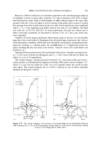
The ‘mode exchange’, already discussed in Section 3.5.1, also arises in the case of artic-
ulated systems, as demonstrated by Sugiyama & Noda (1981) and as shown in Figure 3.77,
where it is seen that the mode loci come very close together before the switch actually
takes place. The Argand diagram for B = 0.50 is identical to one of those originally
obtained by Benjamin (1961a).
4
3
:
2g
1
r UCf = 2. I 23
\2S
.
A
%t$4) 1
Figure 3.77 The ‘mode exchange’ from second- to first-mode flutter for an articulated cantilever
with varying j3 for y = 0: (a) for B increasing, starting with j3 = 0.50; (b) for decreasing, starting
with j3 = 0.55 (Sugiyama & Noda 1981).