
Page 204 - Fluid-Structure Interactions Slender Structure and Axial Flow (Volume 1)
P. 204
186 SLENDER STRUCTURES AND AXIAL FLOW
Lunn (1982) studies the effect of dissipation on two-degree-of-freedom systems, in
particular for B + 0, obtaining similar behaviour to that discussed in Section 3.5.6 for
continuous systems: i.e. severe destabilization due to internal damping (Figure 3.37). He
also conducted a number of experiments, some of which are discussed in Chapter 5 (see
Figure 5.14).
3.8.2 N-degree-of-freedom pipes
One major difference between the continuous and articulated cantilevered systems is
that in the latter, if the pipe is vertical, divergence may occur, while for the continuous
system it has been shown theoretically and confirmed experimentally that divergence is
impossible. The resolution of this difference in behaviour was the motivation of the work
Paidoussis & Deksnis (1970), dramatically entitled ‘the study of a paradox’; ‘paradox’
simply because in the limit, as the number of articulations N -+ 03, one should expect
the articulated system to approach the continuous one in every respect.
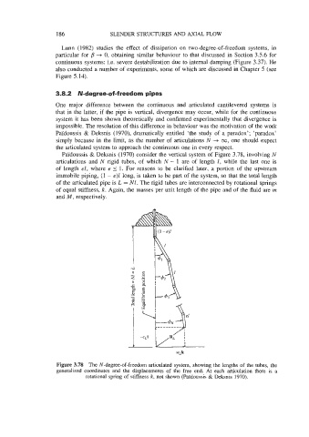
Paidoussis & Deksnis (1970) consider the vertical system of Figure 3.78, involving N
articulations and N rigid tubes, of which N - 1 are of length 2, while the last one is
of length el, where e 5 1. For reasons to be clarified later, a portion of the upstream
immobile piping, (1 - e)Z long, is taken to be part of the system, so that the total length
of the articulated pipe is L = NL. The rigid tubes are interconnected by rotational springs
of equal stiffness, k. Again, the masses per unit length of the pipe and of the fluid are rn
and M, respectively.
Figure 3.78 The N-degree-of-freedom articulated system, showing the lengths of the tubes, the
generalized coordinates and the displacements of the free end. At each articulation there is a
rotational spring of stiffness k, not shown (PaYdoussis & Deksnis 1970).