
Page 251 - Fluid-Structure Interactions Slender Structure and Axial Flow (Volume 1)
P. 251
232 SLENDER STRUCTURES AND AXIAL FLOW
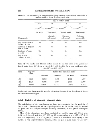
Table 4.2 The characteristics of different outflow-model functions. The schematic presentation of
outflow models is for the first beam mode only.
Type of outflow-model
No model ‘First model’ ‘Second model’ ‘Third model’
( 1 st-order (2nd-order (3rd-order
Characteristics polynomial) polynomial) polynomial)
Zero displacement at Yes Yes Yes Yes
‘infinity’ (t = I)
Continuity of displace- No Yes Yes Yes
ment at outlet
Continuity of slope No No Yes Yes
at outlet
Zero slope at Yes No No Yes
‘infinity’ (6 = I)
Table 4.3 The results with different outflow models for the first terms of the generalized
fluid-dynamic force, Qfi (k = n = 1, i = 1,2,3) with 1 = 2.8, for a long cantilevered pipe
(A = lo”, E = 8.25 x lo5).
Term Plug-flow Refined fluid mechanics model
model
No model 1st model 2nd model 3rd model
1 .ooo 0.99 15 1 .ooo 1.000 1 .000
Q(2) 2.000 0.9941 1.984 2.000 2.000
11
Q(3) 0.8582 -1.879 -2.873 0.8510 0.8222
11
has been adopted throughout this work for calculating the generalized fluid-dynamic forces
for short cantilevered pipes.
4.4.6 Stability of clamped -clamped pipes
The calculations of the eigenfrequencies have been conducted by the methods of
Section 4.4.2. Convergence of the eigenfrequencies by the modal analysis method
is quite fast: for clamped-clamped boundary conditions, N = 7 yields convergent
results.
Most of the calculations have been conducted for metallic pipes with h/(a + h) =
0.10, u = 0.3, a = 0 and A = 10l2, 100 and 10, corresponding to E = 8.25 x lo5, 8.25
and 2.61, respectively. A = (k’GAp/EZp)L2, which is a measure of shear rigidity of the
system, is very large for realistic systems, unless the pipe is quite short. For A = lo’*