Page 291 - Fluid-Structure Interactions Slender Structure and Axial Flow (Volume 1)
P. 291

Reference  -


                   272                SLENDER STRUCTURES AND AXIAL FLOW

                                                                    Fluid supply
                                                                       II
                                                 I
                                  input     8 bit D/A convertex   I   Flow meter
                                   I
                                   I


                                   Dip       8 bit one-chip
                                  switch     microcomputer


                                            8 bit D/A convertet

                                               Amplifier


                                                                      U
                                (a)
                                 Disturbance
                                    \


                                     DisturbanceNalve opened
                                         \           SettlingNalve closed


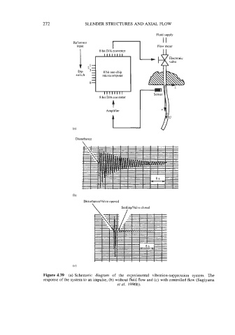
                    Figure 4.39  (a) Schematic  diagram  of  the  experimental  vibration-suppression  system.  The
                    response of the system to an impulse, (b) without fluid flow and (c) with controlled flow (Sugiyama
                                                   et al. 1996b).
   286   287   288   289   290   291   292   293   294   295   296