Page 181 - Formulas and Calculations for Petroleum Engineering
P. 181

174 Formulas and calculations for petroleum engineering


                3.56 Time to pseudo-steady state (single well-circular  3.58 True wellbore storage coefficient (pressure
                   reservoir)                             200       build-up test)                         201
                3.57 Time to reach the semi-steady state for a gas well  3.59 Well flow efficiency (geothermal well)  202
                   in a circular or square drainage area  201   3.60 Well shut-in pressure during buildup (Horner plot)  202


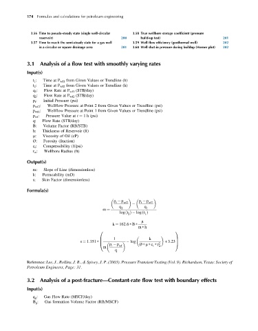
              3.1   Analysis of a flow test with smoothly varying rates

              Input(s)
                 t 1 :  Time at P wf1 from Given Values or Trendline (h)
                 t 2 :  Time at P wf2 from Given Values or Trendline (h)
                 q 1 :  Flow Rate at P wf1 (STB/day)
                 q 2 :  Flow Rate at P wf2 (STB/day)
                 p i :  Initial Pressure (psi)
                 p wf2 :  Wellflow Pressure at Point 2 from Given Values or Trendline (psi)
                 p wf1 :  Wellflow Pressure at Point 1 from Given Values or Trendline (psi)
                 p wf :  Pressure Value at t ¼ 1 h (psi)
                 q:  Flow Rate (STB/day)
                 B:  Volume Factor (RB/STB)
                 h:  Thickness of Reservoir (ft)
                 m:  Viscosity of Oil (cP)
                 Ø:   Porosity (fraction)
                 c t :  Compressibility (1/psi)
                 r w :  Wellbore Radius (ft)

              Output(s)

                 m:   Slope of Line (dimensionless)
                 k:  Permeability (mD)
                 s:  Skin Factor (dimensionless)

              Formula(s)


                                                       p  p wf2    p  p wf1
                                                        i
                                                                    i

                                                         q 2         q 1
                                                  m ¼
                                                          log t ðÞ  log tðÞ
                                                              2
                                                                      1
                                                                    m
                                                      k ¼ 162:6   B
                                                                  m   h
                                                0                                   1

                                                       1                k
                                                B                                   C
                                       s ¼ 1:151   B           log             +3:23 C
                                                @    p  p wf       Ø   m   c   r 2 w  A
                                                                         t
                                                      i
                                                  m
                                                       q
              Reference: Lee, J., Rollins, J. B., & Spivey, J. P. (2003). Pressure Transient Testing (Vol. 9). Richardson, Texas: Society of
              Petroleum Engineers, Page: 31.
              3.2   Analysis of a post-fracture—Constant-rate flow test with boundary effects
              Input(s)
                 q g :  Gas Flow Rate (MSCF/day)
                 B g :  Gas formation Volume Factor (RB/MSCF)
   176   177   178   179   180   181   182   183   184   185   186