
Page 284 - Subyek Teknik Mesin - Forsthoffers Best Practice Handbook for Rotating Machinery by William E Forsthoffer
P. 284
Be st Practice 4 .9 Gear and Coupling Best Practices
based on the shaft taper. This is the axial distance the coupling
must be moved up the shaft. The coupling drive per 0.001" of
shrink fit for the most common shaft tapers is noted below:
Shaft taper Drive per 0.001" shrink
1 1.448mm (0.057")
/ 2
1 / 2 " per foot 0.610mm (0.024")
3
/ 4 " per foot 0.406mm (0.016")
As an example, a hydraulic fit coupling with a 101.5mm (4")
bore requires a 0.008" shrink fit (i.e. the bore diameter is 0.008"
less than the shaft). To expand the coupling bore 0.008", what is
the drive if the shaft taper is:
Fig 4.9.1 Typical coupling hydraulic shrink fit Taper Drive
1 11.582mm (0.456")
/ 2
1
/ 2 " per foot 4.877mm (0.192")
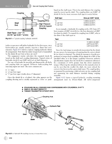
turbo-compressors will utilize hydraulic fits for this reason, since 3 / 4 " per foot 3.251mm (0.128")
hydrocarbon gas, usually present, requires a flame free envi-
ronment. Figure 4.9.1 shows a typical coupling hydraulic shrink Since the load torque is completely transmitted by the shrink
fit arrangement. Note that the entire torque load is transmitted fit, one can see the importance of assuring that the correct shrink
by the shrink fit and that no keys are used! fit (or drive) is obtained. The shrink fit amount is directly pro-
The equipment vendor calculates the required shrink fit portional to torque load capability. If the shrink fit is 50% of the
based on the shaft and coupling dimensions. Typical values of specified value, so is the torque capability! However, industry
hydraulic shrink fit are 0.002 inch/inch of shaft diameter. specifications require that the shrink fit at minimum tolerances
For ease of hydraulic fit assembly and disassembly, all shafts be a minimum of 125% greater than the driver maximum
and coupling hubs are tapered. Different shaft/coupling hub torque. Observing the calculated drives in the example above it
matching tapers are used. The most common are: can be seen that the smaller the shaft, the more critical the
correct drive becomes for a given shaft taper. The coupling drive
/ 2 taper
1
1
/ 2 " per foot taper is measured by positioning a dial indicator on the coupling hub
3
/ 4 " per foot taper (shafts above 4" diameter) and measuring the axial distance traveled during coupling
assembly.
Once the shrink fit is calculated, the value appears on the Figure 4.9.2 shows a typical hydraulic coupling mounting
coupling drawing and is usually expressed as ‘drive’ or ‘push’ arrangement used by Dresser-Rand. All turbo-compressor
Fig 4.9.2 Hydraulic fit coupling (Courtesy of Dresser-Rand Corp)
258