
Page 280 - Subyek Teknik Mesin - Forsthoffers Best Practice Handbook for Rotating Machinery by William E Forsthoffer
P. 280
Be st Practice 4 .8 Gear and Coupling Best Practices
Coupling
B.P. 4.7. Supporting Material
Driven shaft/coupling fit
The driven shaft
The coupling system The coupling spacer system
Lubrication (if required)
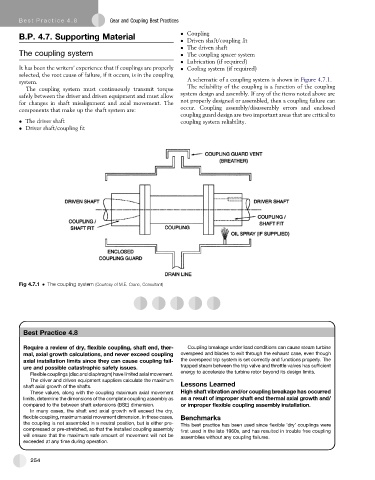
It has been the writers’ experience that if couplings are properly Cooling system (if required)
selected, the root cause of failure, if it occurs, is in the coupling
system. A schematic of a coupling system is shown in Figure 4.7.1.
The coupling system must continuously transmit torque The reliability of the coupling is a function of the coupling
safely between the driver and driven equipment and must allow system design and assembly. If any of the items noted above are
for changes in shaft misalignment and axial movement. The not properly designed or assembled, then a coupling failure can
components that make up the shaft system are: occur. Coupling assembly/disassembly errors and enclosed
coupling guard design are two important areas that are critical to
The driver shaft coupling system reliability.
Driver shaft/coupling fit
Fig 4.7.1 The coupling system (Courtesy of M.E. Crane, Consultant)
Best Practice 4.8
Require a review of dry, flexible coupling, shaft end, ther- Coupling breakage under load conditions can cause steam turbine
mal, axial growth calculations, and never exceed coupling overspeed and blades to exit through the exhaust case, even though
axial installation limits since they can cause coupling fail- the overspeed trip system is set correctly and functions properly. The
ure and possible catastrophic safety issues. trapped steam between the trip valve and throttle valves has sufficient
energy to accelerate the turbine rotor beyond its design limits.
Flexible couplings (disc and diaphragm) have limited axial movement.
The driver and driven equipment suppliers calculate the maximum
shaft axial growth of the shafts. Lessons Learned
These values, along with the coupling maximum axial movement High shaft vibration and/or coupling breakage has occurred
limits, determine the dimensions of the complete coupling assembly as as a result of improper shaft end thermal axial growth and/
compared to the between shaft extensions (BSE) dimension. or improper flexible coupling assembly installation.
In many cases, the shaft end axial growth will exceed the dry,
flexible coupling, maximum axial movement dimension. In these cases, Benchmarks
the coupling is not assembled in a neutral position, but is either pre- This best practice has been used since flexible ‘dry’ couplings were
compressed or pre-stretched, so that the installed coupling assembly first used in the late 1960s, and has resulted in trouble free coupling
will ensure that the maximum safe amount of movement will not be assemblies without any coupling failures.
exceeded at any time during operation.
254