
Page 278 - Subyek Teknik Mesin - Forsthoffers Best Practice Handbook for Rotating Machinery by William E Forsthoffer
P. 278
Be st Practice 4 .6 Gear and Coupling Best Practices
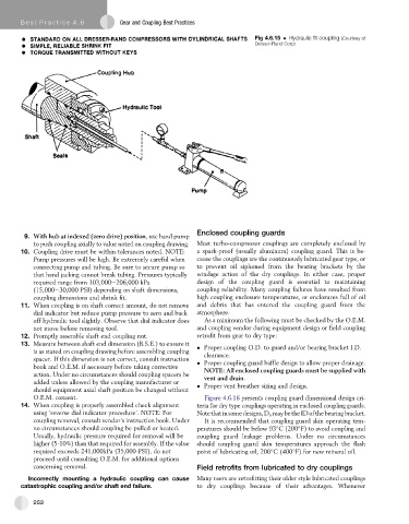
Fig 4.6.15 Hydraulic fit coupling (Courtesy of
Dresser-Rand Corp)
Enclosed coupling guards
9. With hub at indexed (zero drive) position, use hand pump
to push coupling axially to value noted on coupling drawing. Most turbo-compressor couplings are completely enclosed by
10. Coupling drive must be within tolerances noted. NOTE: a spark-proof (usually aluminum) coupling guard. This is be-
Pump pressures will be high. Be extremely careful when cause the couplings are the continuously lubricated gear type, or
connecting pump and tubing. Be sure to secure pump so to prevent oil siphoned from the bearing brackets by the
that hand jacking cannot break tubing. Pressures typically windage action of the dry couplings. In either case, proper
required range from 103,000e206,000 kPa design of the coupling guard is essential to maintaining
(15,000e30,000 PSI) depending on shaft dimensions, coupling reliability. Many coupling failures have resulted from
coupling dimensions and shrink fit. high coupling enclosure temperatures, or enclosures full of oil
11. When coupling is on shaft correct amount, do not remove and debris that has entered the coupling guard from the
dial indicator but reduce pump pressure to zero and back atmosphere.
off hydraulic tool slightly. Observe that dial indicator does As a minimum the following must be checked by the O.E.M.
not move before removing tool. and coupling vendor during equipment design or field coupling
12. Promptly assemble shaft end coupling nut. retrofit from gear to dry type:
13. Measure between shaft end dimension (B.S.E.) to ensure it
is as stated on coupling drawing before assembling coupling Proper coupling O.D. to guard and/or bearing bracket I.D.
clearance.
spacer. If this dimension is not correct, consult instruction Proper coupling guard baffle design to allow proper drainage.
book and O.E.M. if necessary before taking corrective NOTE: All enclosed coupling guards must be supplied with
action. Under no circumstances should coupling spacers be vent and drain.
added unless allowed by the coupling manufacturer or Proper vent breather sizing and design.
should equipment axial shaft position be changed without
O.E.M. consent. Figure 4.6.16 presents coupling guard dimensional design cri-
14. When coupling is properly assembled check alignment teria for dry type couplings operating in enclosed coupling guards.
using ‘reverse dial indicator procedure’. NOTE: For Notethatinsomedesigns,D o maybetheIDofthebearingbracket.
coupling removal, consult vendor’s instruction book. Under It is recommended that coupling guard skin operating tem-
no circumstances should coupling be pulled or heated. peratures should be below 93 C (200 F) to avoid coupling and
Usually, hydraulic pressure required for removal will be coupling guard leakage problems. Under no circumstances
higher (5-10%) than that required for assembly. If the value should coupling guard skin temperatures approach the flash
required exceeds 241,000kPa (35,000 PSI), do not point of lubricating oil, 200 C (400 F) for new mineral oil.
proceed until consulting O.E.M. for additional options
concerning removal. Field retrofits from lubricated to dry couplings
Incorrectly mounting a hydraulic coupling can cause Many users are retrofitting their older style lubricated couplings
catastrophic coupling and/or shaft end failure. to dry couplings because of their advantages. Whenever
252