
Page 274 - Subyek Teknik Mesin - Forsthoffers Best Practice Handbook for Rotating Machinery by William E Forsthoffer
P. 274
Be st Practice 4 .6 Gear and Coupling Best Practices
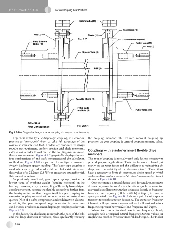
Fig 4.6.6 Single diaphragm spacer coupling (Courtesy of Lucas Aerospace)
Regardless of the type of diaphragm coupling, it is common the coupling moment. The reduced moment coupling ap-
practice to ‘pre-stretch’ them to take full advantage of the proaches the gear coupling in term of coupling moment value.
maximum available end float. Readers are cautioned to always
require that equipment vendors provide axial shaft movement
calculations in order to confirm that the coupling maximum end Couplings with elastomer insert flexible drive
float is not exceeded. Figure 4.6.7 graphically displays the var- members
ious combinations of end shaft movement and the calculation This type of coupling is normally used only for low horsepower,
method, and Figure 4.6.8 is a picture of a multiple, convoluted general purpose applications. Their limitations are based pri-
(wavy) diaphragm spacer coupling. This latter type coupling is marily on the wear factor and the difficulty in maintaining the
used whenever large values of axial end float exist. Axial end shape and concentricity of the elastomer insert. These items
float values of 22.2mm (0.875") or greater are attainable with have a tendency to limit the maximum design speed at which
this type of coupling. such couplings can be operated. A typical ‘jaw and spider’ type is
As previously mentioned, gear type couplings provide the shown in Figure 4.6.10.
lowest value of overhung weight (coupling moment) on the One exception is a special design used for synchronous motor
bearing. However, a dry type coupling will usually have a higher driven compressor trains. A characteristic of synchronous motors
coupling moment, because the flexible assembly is farther from is a variable oscillating torque that decreases linearly in frequency
the bearing centerline than the gear teeth in a gear coupling. An from 2 line frequency (50Hz or 60Hz) at 0 rpm, to zero fre-
excessive coupling moment will reduce the second natural fre- quency at rated rpm. Figure 4.6.11 shows a plot of motor rpm vs.
quency (N c2 ) of a turbo-compressor, and could move it close to, transient torsional excitation frequency. The excitation frequency
or within, the operating speed range. A solution in these cases inherent in all synchronous motors will excite all torsional natural
can be to use a reduced moment diaphragm coupling as shown in frequencies present between 2 line frequency and 0 rpm.
Figure 4.6.9. When the motor torsional excitation frequency briefly
In this design, the diaphragm is moved to the back of the hub, coincides with a torsional natural frequency, torque values can
and the flange diameter is reduced, thus significantly reducing amplifytoasmuchasfiveorsixtimesfullloadtorque.The‘Holset’
248