
Page 276 - Subyek Teknik Mesin - Forsthoffers Best Practice Handbook for Rotating Machinery by William E Forsthoffer
P. 276
Be st Practice 4 .6 Gear and Coupling Best Practices
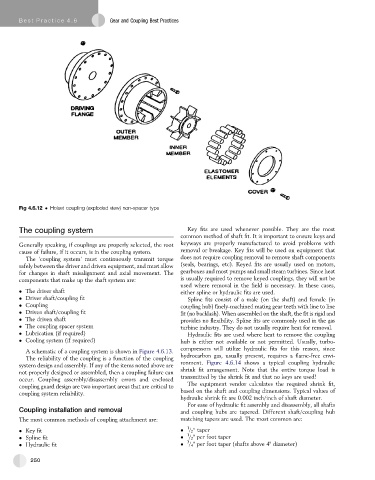
Fig 4.6.12 Holset coupling (exploded view) non-spacer type
The coupling system Key fits are used whenever possible. They are the most
common method of shaft fit. It is important to ensure keys and
Generally speaking, if couplings are properly selected, the root keyways are properly manufactured to avoid problems with
cause of failure, if it occurs, is in the coupling system. removal or breakage. Key fits will be used on equipment that
The ‘coupling system’ must continuously transmit torque does not require coupling removal to remove shaft components
safely between the driver and driven equipment, and must allow (seals, bearings, etc). Keyed fits are usually used on motors,
for changes in shaft misalignment and axial movement. The gearboxes and most pumps and small steam turbines. Since heat
components that make up the shaft system are: is usually required to remove keyed couplings, they will not be
used where removal in the field is necessary. In these cases,
The driver shaft either spline or hydraulic fits are used.
Driver shaft/coupling fit Spline fits consist of a male (on the shaft) and female (in
Coupling coupling hub) finely-machined mating gear teeth with line to line
Driven shaft/coupling fit fit (no backlash). When assembled on the shaft, the fitis rigidand
The driven shaft provides no flexibility. Spline fits are commonly used in the gas
The coupling spacer system turbine industry. They do not usually require heat for removal.
Lubrication (if required) Hydraulic fits are used where heat to remove the coupling
Cooling system (if required) hub is either not available or not permitted. Usually, turbo-
compressors will utilize hydraulic fits for this reason, since
A schematic of a coupling system is shown in Figure 4.6.13.
The reliability of the coupling is a function of the coupling hydrocarbon gas, usually present, requires a flame-free envi-
system design and assembly. If any of the items noted above are ronment. Figure 4.6.14 shows a typical coupling hydraulic
not properly designed or assembled, then a coupling failure can shrink fit arrangement. Note that the entire torque load is
occur. Coupling assembly/disassembly errors and enclosed transmitted by the shrink fit and that no keys are used!
coupling guard design are two important areas that are critical to The equipment vendor calculates the required shrink fit,
coupling system reliability. based on the shaft and coupling dimensions. Typical values of
hydraulic shrink fit are 0.002 inch/inch of shaft diameter.
For ease of hydraulic fit assembly and disassembly, all shafts
Coupling installation and removal and coupling hubs are tapered. Different shaft/coupling hub
The most common methods of coupling attachment are: matching tapers are used. The most common are:
1
Key fit / 2 taper
1
Spline fit / 2 " per foot taper
3
Hydraulic fit / 4 " per foot taper (shafts above 4" diameter)
250