
Page 273 - Subyek Teknik Mesin - Forsthoffers Best Practice Handbook for Rotating Machinery by William E Forsthoffer
P. 273
Gear and Coupling Best Practices Be st Practice 4.6
We can assume then, that if we use a coupling with a 15 cm
(6 inch) pitch diameter gear mesh, which is transmitting 28,250
Ncm (25,000 inch-pounds) of torque and has a break-away
friction factor of 0.30, the axial force required to move the
gear mesh to a new axial position would be 11,300 N (2,500
pounds). Adjacent thrust bearings must be capable of handling
this force in addition to the machine’s normal calculated thrust
forces. Machinery train designers and users must be aware of
this, and make provisions for it in the built-in safety factors of
the thrust bearings and machinery mounting design.
The machinery user must know that the same phenomenon
has an effect on vibration when machinery is operated with ex-
cessive misalignment. The gear mesh position must change with
each revolution of the shaft to correct for the misalignment. This
results in counter axial forces on a cyclic basis, since the mesh is
moving in opposite directions on each side of the coupling. Vi-
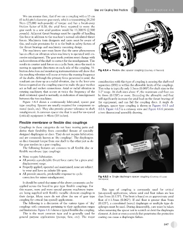
bration detection and monitoring instrumentation will show that Fig 4.6.4 Flexible disc spacer coupling (Courtesy of Rexnord)
the resulting vibration will occur at twice the running frequency
of the shafts. Although the primary force generated is axial, the
resultant can show up as a radial vibration, due to the lever arm consideration with this type of coupling is assuring the shaft end
forces required on the coupling spacer to make the gear meshes separation (BSE) is within the allowable limits of the couplings.
act as ball and socket connections. Axial or radial vibration in This value is typically only 1.5mm (0.060") for shaft sizes in the
rotating machinery that occurs at twice the frequency of the 1-2" range. At shaft sizes above 4", the maximum end float can
shaft rotational speed is normally an indication of misalignment be 6mm (0.150") or more. Exceeding the allowable end float
between the two machines. will significantly increase the axial load on the thrust bearings of
Figure 4.6.4 shows a continuously lubricated, spacer gear the equipment, and can fail the coupling discs. A single di-
type coupling. Spacers are usually required for component re- aphragm, spacer type coupling is shown in Figures 4.6.5 and
moval (seals, etc). They also provide greater tolerance to shaft 4.6.6. Figure 4.6.5 is a cutaway view and Figure 4.6.6 presents
misalignment. A common spacer size that is used for un-spared a two dimensional assembly drawing.
(critical) equipment is 46cm (18 inches).
Flexible membrane or flexible disc couplings
Couplings in these categories do not have moving parts and
derive their flexibility from controlled flexure of specially
designed diaphragms or discs. They do not require lubrication
and are commonly known as ‘dry couplings’. The diaphragms
or discs transmit torque from one shaft to the other just as do
the gear meshes in a gear coupling.
The following features are common to all flexible disc or
flexible membrane type couplings:
None require lubrication.
All provide a predictable thrust force curve for a given axial
displacement range.
Properly applied, operated and maintained, none are subject
to wear and have an infinite life span.
All provide smooth, predictable response to cyclic
correction for minor misalignment. Fig 4.6.5 Single diaphragm spacer coupling (Courtesy of Lucas
Aerospace)
It should be noted that none of the above comments can be
applied across the board to gear type flexible couplings. For
this reason, more and more special purpose machinery trains This type of coupling is commonly used for critical
are being supplied with flexible metallic element couplings in (un-spared) applications, where axial end float values are less
their design. Many users do not allow the use of gear type than 5mm (0.125"). This limit is based on an approximate axial
coupling for critical (un-spared) applications. float of 1.5mm (0.062"). If end float is greater than 5mm
The following is a discussion of the various types of ‘dry’ (0.125"), a convoluted (wavy) diaphragm or multiple type di-
couplings with comments pertaining to their application ranges aphragm must be used. During disassembly, care must be taken
and limitations. Figure 4.6.4 shows a typical flexible disc coupling. when removing the spacer not to scratch or dent the diaphragm
This is the most common type and is generally used for element. A dent or even a scratch that penetrates the protective
general purpose applications (pumps, fans, etc). The major coating can cause a diaphragm failure.
247