
Page 271 - Subyek Teknik Mesin - Forsthoffers Best Practice Handbook for Rotating Machinery by William E Forsthoffer
P. 271
Gear and Coupling Best Practices Be st Practice 4.6
Best
Best Practice 4.6Practice 4.6Practice 4.6
Best
Replace oil lubricated gear couplings that have experi- Lessons Learned
enced lock-up (high vibration causing bearing damage) Many existing critical machine trains require a yearly shutdown to
with flexible disc couplings. clean gear coupling teeth after high vibration shutdowns or
Oil lubricated gear couplings, used prior to the 1970s, can experi- bearing failures necessitate shutdown. Time for shutdown can
ence lock-up, since they will centrifuge their lubrication oil into the exceed three days. Present daily revenues for critical (unspared)
meshing teeth, which can render the coupling rigid. compressor trains can exceed $1 MM/day.
Regardless of the filter size (even as low as 1 micron), lock-up can
occur on large gear couplings and/or at high speeds. Benchmarks
Replacement of gear couplings can be accomplished successfully This best practice has been used since the 1990s to remove the ne-
as long as all of the following items are considered and confirmed to be cessity of a yearly gear coupling PMs, and to prevent bearing damage
designed correctly with the new dry coupling: resulting from coupling lock-up. The modification cost can be easily
Torsional natural frequencies justified if yearly shutdowns are required for gear coupling cleaning.
Lateral natural frequencies (critical speeds) and rotor response
Coupling guard internal clearance to coupling hub flange OD
B.P. 4.6. Supporting Material a large axial position change tolerance compared to flexible
element types.
The coupling function
Types
The function of a flexible coupling is to transmit torque from the
driver to the driven machine, while making allowances for minor The following is a list of various types of flexible couplings:
shaft misalignment and shaft end position changes between the Gear couplings
two machines. The design of the coupling should provide for Continuous lubrication
transmission of the required torque at the required speed, with
Grease packed
a minimum of extraneous forces and perturbations being Flexible membrane or flexible disc couplings
exerted on either the driver or driven shaft. Shaft misalignment Single membrane type
exists when the centerlines of two shafts that are joined by Multiple membrane or multiple disc type
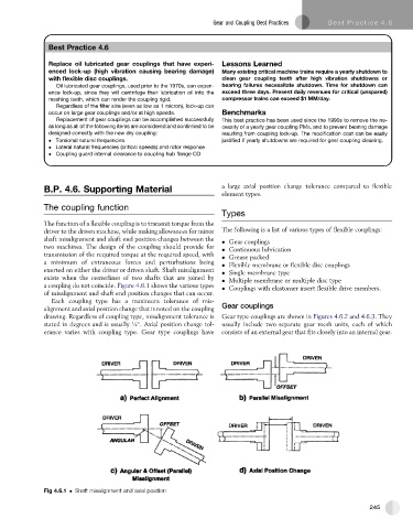
a coupling do not coincide. Figure 4.6.1 shows the various types Couplings with elastomer insert flexible drive members.
of misalignment and shaft end position changes that can occur.
Each coupling type has a maximum tolerance of mis-
alignment and axial position change that is noted on the coupling Gear couplings
drawing. Regardless of coupling type, misalignment tolerance is Gear type couplings are shown in Figures 4.6.2 and 4.6.3. They
stated in degrees and is usually ¼ . Axial position change tol- usually include two separate gear mesh units, each of which
erance varies with coupling type. Gear type couplings have consists of an external gear that fits closely into an internal gear.
Fig 4.6.1 Shaft misalignment and axial position
245