
Page 266 - Subyek Teknik Mesin - Forsthoffers Best Practice Handbook for Rotating Machinery by William E Forsthoffer
P. 266
Be st Practice 4 .5 Gear and Coupling Best Practices
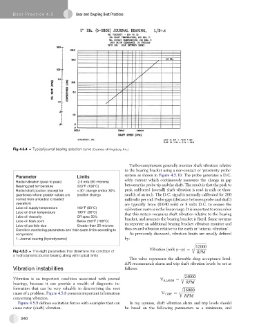
Fig 4.5.4 Typical journal bearing selection curve (Courtesy of Kingsbury, Inc.)
Turbo-compressors generally monitor shaft vibration relative
to the bearing bracket using a non-contact or ‘proximity probe’
system as shown in Figure 4.5.10. The probe generates a D.C.
Parameter Limits
eddy current which continuously measures the change in gap
Radial vibration (peak to peak) 2.5 mils (60 microns)
Bearing pad temperature 220°F (108°C) between the probe tip and the shaft. The result is that the peak to
Radial shaft position (except for >30° change and/or 30% peak unfiltered (overall) shaft vibration is read in mils or thou-
gearboxes where greater values are position change sandth of an inch. The D.C. signal is normally calibrated for 200
normal from unloaded to loaded millivolts per mil. Probe gaps (distance between probe and shaft)
operation) are typically 1mm (0.040 mils) or 8 volts D.C. to ensure the
Lube oil supply temperature 140°F (60°C)
calibrationcurve is in the linear range. It is important to remember
Lube oil drain temperature 190°F (90°C) that this system measures shaft vibration relative to the bearing
L u b e l i o s i v c o y t i s O f f s p e c 5 0 %
bracket, and assumes the bearing bracket is fixed. Some systems
Lube oil flash point Below 200°F (100°C)
Lube oil particle size Greater than 25 microns incorporate an additional bearing bracket vibration monitor and
Condition monitoring parameters and their alarm limits according to thus record vibration relative to the earth or ‘seismic vibration’.
component: As previously discussed, vibration limits are usually defined
1. Journal bearing (hydrodynamic) by:
r ffiffiffiffiffiffiffiffiffiffiffiffiffiffi
12000
Vibration ðmils pepÞ¼
Fig 4.5.5 The eight parameters that determine the condition of RPM
a hydrodynamic journal bearing along with typical limits
This value represents the allowable shop acceptance level.
API recommends alarm and trip shaft vibration levels be set as
Vibration instabilities follows:
r ffiffiffiffiffiffiffiffiffiffiffiffiffiffi
24000
Vibration is an important condition associated with journal V ALARM ¼
bearings, because it can provide a wealth of diagnostic in- RPM
formation that can be very valuable in determining the root r ffiffiffiffiffiffiffiffiffiffiffiffiffiffi
36000
cause of a problem. Figure 4.5.8 presents important information V TRIP ¼ RPM
concerning vibration.
Figure 4.5.9 defines excitation forces with examples that can In my opinion, shaft vibration alarm and trip levels should
cause rotor (shaft) vibration. be based on the following parameters as a minimum, and
240