
Page 265 - Subyek Teknik Mesin - Forsthoffers Best Practice Handbook for Rotating Machinery by William E Forsthoffer
P. 265
Gear and Coupling Best Practices Be st Practice 4.5
Straight sleeve bearings are used for low shaft speeds (less
than 5,000 rpm) or for older turbo-compressor designs.
Frequently, they are modified to incorporate a pressure dam,
in the direction of rotation. The pressure dam must be
positioned in the top half of the bearing to increase the load
vector. This action ensures that the tangential force vector
will be small relative to the load vector, thus preventing shaft
instability. It should be noted that incorrectly assembling the
pressure dam in the lower half of the bearing would render
this type of bearing unstable. When shaft speed is high, other
alternatives to prevent rotor instabilities are noted in
Figure 4.5.2.
Shown are examples of anti-whirl bearings. The most
common types of these bearings are the three and four lobe
design. Elliptical and offset bearing designs do prevent in-
stabilities, but tend to increase shaft vibration if the load vector
passes through the major axis of the bearing. These types of
bearings may have to be rotated in the bearing brackets to pre-
vent this occurrence.
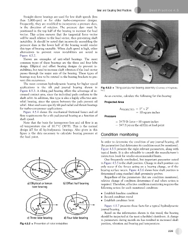
The most common hydrodynamic bearing for higher speed
applications is the tilt pad journal bearing shown in Fig 4.5.3 Tilting pad journal bearing assembly (Courtesy of Kingsbury,
Figure 4.5.3. A tilting pad bearing offers the advantage of in- Inc.)
creased contact area, since the individual pads conform to the As an exercise, calculate the following for this bearing:
shaft orbit. In addition, this type is also a highly effective anti-
whirl bearing, since the spaces between the pads prevent oil Projected Area
whirl. Most end users specify tilt pad radial and thrust bearings
for turbo-compressor applications. A PROJECTED ¼ 5 2 00
00
Figure 4.5.4 shows the mechanical frictional losses and oil ¼ 10 square inches
flow requirements for a tilt pad journal bearing as a function of Pressure
shaft speed.
Note that the basis for horsepower loss and oil flow is an ¼ 3479 lb forceO10 square inches
oil temperature rise of 16.7 C(30 F). This is the normal ¼ 347:9 psi on the oil film at load point
design DT for all hydrodynamic bearings. Also given in this
figure is the data necessary to calculate bearing pressure at Condition monitoring
the load point.
In order to determine the condition of any journal bearing, all
the parameters that determine its condition must be monitored.
Figure 4.5.5 presents the eight relevant parameters, along with
typical limits. It is also advisable to consult the manufacturer’s
instruction book for vendor-recommended limits.
One frequently overlooked, but important parameter noted
in Figure 4.5.5 is the shaft position. Change in shaft position can
only occur if the forces acting on a bearing change, or if the
bearing surface wears. Figure 4.5.6 shows how shaft position is
determined using standard shaft proximity probes.
Regardless of the parameters that are condition monitored,
relative change of condition determines if and when action is
required. Therefore, effective condition monitoring requires the
following action for each monitored condition:
Establish baseline condition
Record condition trend
Establish condition limit
Figure 4.5.7 presents these facts for a typical hydrodynamic
journal bearing.
Based on the information shown in this trend, the bearing
should be inspected at the next scheduled shutdown. A change
in parameters during month six has resulted in increased shaft
Fig 4.5.2 Prevention of rotor instabilities position, vibration and bearing pad temperature.
239