
Page 264 - Subyek Teknik Mesin - Forsthoffers Best Practice Handbook for Rotating Machinery by William E Forsthoffer
P. 264
Be st Practice 4 .5 Gear and Coupling Best Practices
Figure 4.4.4 shows the reaction force transmission path of and external spur gears. Figure 4.4.5 shows the reaction forces
a gear radial bearing. The entire gear unit system contributes to that act on a helical pinion tooth.
the support of transmitted loads. A change in the load carrying Once the total radial load, W RT , is known, the individual
capability of any of the items noted in the figure can result in radial bearing forces can be determined by statics mechanics; as
reduced gear unit reliability. shown in Figure 4.4.6.
The axial load, W A , is calculated directly as shown in
Gear reaction forces at bearings Figure 4.4.5, and can be applied to either the gear shaft,
pinion shaft, or divided between the gear and pinion shaft.
Since between-bearing helical gears are the most common type Most gear designs absorb all thrust on the gear shaft (low
on site, only this type will be covered. However, the relations speed), since this usually results in the lowest thrust bearing
discussed, with minor modifications, will also apply to internal losses.
Best
Best
Best Practice 4.5Practice 4.5Practice 4.5
Monitor the gear centerline shaft position to condition Lessons Learned
monitor radial bearing wear and load (attitude) angle. Critical integral gear compressors have required emer-
Gearbox radial bearings are the highest loaded bearings in any type gency shutdown due to excessive radial bearing wear that
of machinery and approach the limits of oil film pressure (3500kpa or did not cause high levels of vibration prior to shutdown
500psi). (high vibration occurred when Babbitt material was ex-
If the area of the radial bearings is increased, bearing instability will cessively worn).
occur during low load at start-up (see B.P. 4.4). Heavily loaded radial bearings do not exhibit high vibration, and can
Therefore, bearing life is limited, and is lower than radial bearings in
go undetected if shaft position is not monitored, and bearing pad
other applications (pumps, compressors, turbines, etc.).
temperature probes are not located at the load point of the bearing.
Shaft centerline position ismonitored by two proximityprobes thatare
mounted at each radial bearing. They will record the position of the shaft
and therefore the load angle of the shaft in the bearing. The load angle in Benchmarks
This best practice has been used since the 1980s to optimize highly
gear applications changes with transmitted torque (power/speed).
loaded gear radial bearing life, by predicting and recommending
Trending shaft centerline position will enable condition monitoring
machine shutdowns at convenient times, thus eliminating costly
of bearing wear (increasing shaft centerline position) and determination
emergency shutdowns.
of the position of the load angle.
When the load angle lies in the major axis of an elliptical (lemon bore or
offset sleeve bearing)vibration,instabilitiescanoccur (oil whirloroil whip).
B.P. 4.5. Supporting Material
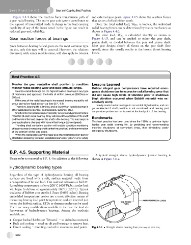
A typical straight sleeve hydrodynamic journal bearing is
Please refer to material in B.P. 4.4 in addition to the following: shown in Figure 4.5.1.
Hydrodynamic bearing types
Regardless of the type of hydrodynamic bearing, all bearing
surfaces are lined with a soft, surface material made from
a composition of tin and lead. This material is known as Babbitt.
Its melting temperature is above 200 C (400 F), but under load
will begin to deform at approximately 160 C (320 F). Typical
thickness of Babbitt over steel is 1.5mm (0.060 inches). Bearing
embedded temperature probes are a most effective means of
measuring bearing load point temperature, and are inserted just
below the Babbitt surface. RTDs or thermocouples can be used.
There are many modifications available to increase the load ef-
fectiveness of hydrodynamic bearings. Among the methods
available are:
Copper backed Babbitt or ‘Trimetal’ e to aid in heat removal
Back pad cooling e used on tilt pad bearings to remove heat
Direct cooling e directing cool oil to maximum load points Fig 4.5.1 Straight sleeve bearing liner (Courtesy of Elliott Co.)
238