
Page 262 - Subyek Teknik Mesin - Forsthoffers Best Practice Handbook for Rotating Machinery by William E Forsthoffer
P. 262
Be st Practice 4 .4 Gear and Coupling Best Practices
Best
Best Practice 4.4Practice 4.4Practice 4.4
Best
Correct un-loaded gearbox vibration problems, which draft (ID) fan applications, it may be necessary to increase inlet or
typically occur during start-up, by limiting bypass (spill- outlet damper.
)
back) valve stroke to partially load the gear radial
bearings. Lessons Learned
90% or more of radial bearing loading in gearboxes is produced by Many compressor train gears experience high vibration
the transmitted torque (power/speed). during start-up, and in most cases the cause can be traced
Since the radial bearing area is designed for the maximum trans- to oversized bypass valves that are operated fully open.
mitted torque, start-up loads may not produce sufficient force and
corresponding oil wedge to stabilize the gear rotors. Benchmarks
Limiting the opening of the bypass valves will increase the This best practice has been used since 1990 to correct high gearbox
gearbox load and stabilize the gear rotors to reduce vibration during vibrations during start-up, and eliminate plant start-up delays.
low load (start-up conditions). In forced draft (FD) and induced )
Increase damper opening for FD and ID fans.
B.P. 4.4 Supporting Material vented on shutdown). This is an important fact to consider when
gear vibration and/or noise are observed at start-up, shutdown or
under off-design conditions. Figure 4.4.3 presents this impor-
Gear reaction (bearing) forces tant consideration.
Since the transmitted torque loads will be considerably less,
When considering reaction forces, one must consider the entire the gear reaction forces will be considerably less and the com-
gear system, from the gear mesh to the gear foundation. The ponent stresses and pressures will be less. This is exactly why
transmission of torque load through the gear rotors is shown in gear meshes are noisy at start-up, when vibration increases and
Figure 4.4.1, assuming a speed increaser. bearings can become unstable.
The amount of torque that is transmitted depends on the
operating conditions (start-up, rated load, off-design load,
shutdown, etc.).
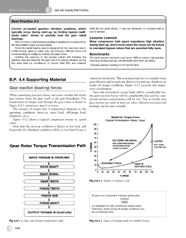
Figure 4.4.2 shows a typical compressor torque vs. speed
curve.
Note that the start-up condition is always at low load, and
frequently the shutdown condition will be at low load (if case is
Fig 4.4.2 Speed vs. torque curve
All gear unit component stresses (pressures)
FORCE
AREA
are designed for rate (maximum) torque loads.
Therefore, loads during off-design conditions can
be considerably less.
Fig 4.4.1 Gear rotor torque transmission path Fig 4.4.3 Gear unit design basis for reaction forces
236