
Page 272 - Subyek Teknik Mesin - Forsthoffers Best Practice Handbook for Rotating Machinery by William E Forsthoffer
P. 272
Be st Practice 4 .6 Gear and Coupling Best Practices
There is a common disadvantage in all gear type flexible
couplings. Any gear mesh has a break-away friction factor in the
axial direction. This is caused by the high contact force between
the two sets of gear teeth. The result is that the forces imposed
on the driver and driven shafts are not totally predictable, and
are sometimes higher than desired due to the quality of the
tooth machine surfaces, and the inevitable build up of sludge or
foreign material in the tooth mesh during extended service.
These forces are detrimental to the ability of the coupling to
make the required corrections for misalignment but, more im-
portantly, can have a disastrous effect on the ability of the
coupling to correct for thermal or thrust force changes between
the driver and driven machines.
Both coupling manufacturers and users have long been aware
of this problem, and have used many methods to minimize the
effect. Some of these methods are:
Reduction of the forces between the gear teeth by increasing
the pitch diameter of the gear mesh. This is often self-
defeating, in that it results in increased size of the coupling
and the coupling weight.
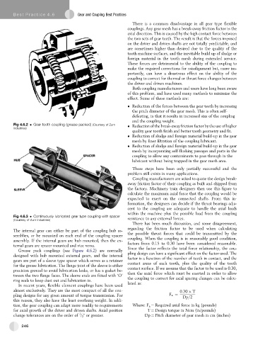
Fig 4.6.2 Gear tooth coupling (grease packed) (Courtesy of Zurn Reduction of the break-away friction factor by the use of higher
Industries)
quality gear tooth finish and better tooth geometry and fit.
Reduction of sludge and foreign material build-up in the gear
mesh by finer filtration of the coupling lubricant.
Reduction of sludge and foreign material build-up in the gear
mesh by incorporating self-flushing passages and ports in the
coupling to allow any contaminants to pass through in the
lubricant without being trapped in the gear mesh area.
These steps have been only partially successful and the
problem still exists in many applications.
Coupling manufacturers are asked to quote the design break-
away friction factor of their coupling as built and shipped from
the factory. Machinery train designers then use this figure to
calculate the maximum axial force that the coupling would be
expected to exert on the connected shafts. From this in-
formation, the designers can decide if the thrust bearings adja-
cent to the coupling are adequate to handle the axial loads
within the machine plus the possible load from the coupling
Fig 4.6.3 Continuously lubricated gear type coupling with spacer
(Courtesy of Zurn Industries) resistance to any external forces.
There has been much discussion, and some disagreement,
regarding the friction factor to be used when calculating
The internal gear can either be part of the coupling hub as-
semblies, or be mounted on each end of the coupling spacer the possible thrust forces that could be transmitted by the
assembly. If the internal gears are hub mounted, then the ex- coupling. When the coupling is in reasonably good condition,
ternal gears are spacer mounted and vice versa. factors from 0.15 to 0.30 have been considered reasonable.
Grease pack couplings (see Figure 4.6.2) are normally Since the factor reflects the total force relationship, the cou-
designed with hub mounted external gears, and the internal pling design can have a significant effect on the factor used. The
gears are part of a sleeve type spacer which serves as a retainer factor is a function of the number of teeth in contact, and the
contact areas of each tooth, plus the quality of the tooth
for the grease lubrication. The flange joint of the sleeve is either
precision ground to avoid lubrication leaks, or has a gasket be- contact surface. If we assume that the factor to be used is 0.30,
then the axial force which must be exerted in order to allow
tween the two flange faces. The sleeve ends are fitted with ‘O’
ring seals to keep dust out and lubrication in. the coupling to correct for axial spacing changes can be calcu-
In recent years, flexible element couplings have been used lated as:
almost exclusively. They are the most compact of all the cou- 0:30 T
pling designs for any given amount of torque transmission. For F a ¼ Dp=2
this reason, they also have the least overhung weight. In addi-
tion, the gear coupling can adapt more readily to requirements Where: F a ¼ Required axial force in kg (pounds)
for axial growth of the driver and driven shafts. Axial position T ¼ Design torque in Ncm (in/pounds)
1
change tolerances are on the order of / 2 " or greater. Dp ¼ Pitch diameter of gear mesh in cm (inches)
246