
Page 277 - Subyek Teknik Mesin - Forsthoffers Best Practice Handbook for Rotating Machinery by William E Forsthoffer
P. 277
Gear and Coupling Best Practices Be st Practice 4.6
Fig 4.6.13 The coupling system (Courtesy of M.E. Crane, Consultant)
fit (or drive) is obtained. The shrink fit amount is directly pro-
portional to torque load capability. If the shrink fit is 50% of the
specified value, so is the torque capability! However, industry
specifications require that the shrink fit at minimum tolerances be
a minimum of 125% greater than the driver maximum torque.
Observing the calculated drives in the example above, it can be
seen that the smaller the shaft, the more critical the correct drive
becomes for a given shaft taper. The coupling drive is measured by
positioning a dial indicator on the coupling hub and measuring the
axial distance traveled during coupling assembly.
Figure 4.6.15 shows a typical hydraulic coupling mounting
arrangement used by Dresser-Rand. All turbo-compressor
manufacturers use similar arrangements. There are some slight
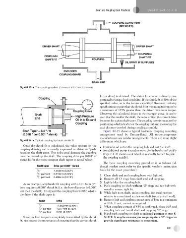
Fig 4.6.14 Typical coupling hydraulic shrink fit
differences which are:
Once the shrink fit is calculated, the value appears on the
Hydraulic oil enters the coupling hub and not the shaft.
coupling drawing and is usually expressed as ‘drive’ or ‘push’ An additional pump is used to move the hydraulic tool axially
based on the shaft taper. This is the axial distance the coupling (Figure 4.39 shows a nut which is manually turned to push
must be moved up the shaft. The coupling drive per 0.001" of the coupling axially).
shrink fit for the most common shaft tapers is noted below:
The basic coupling mounting procedure is as follows (al-
Shaft taper Drive per 0.001 shrink though readers must refer to the specific vendor’s instruction
00
book for the exact procedure):
1 1.448mm (0.057")
/ 2
1
/ 2 " per foot 0.610mm (0.024")
3 1. Clean shaft end and coupling bore with light oil.
/ 4 " per foot 0.406mm (0.016")
2. Remove all ‘O’ rings from shaft end and coupling.
3. Lightly blue the coupling hub.
As an example, a hydraulic fit coupling with a 101.5mm (4") 4. Push coupling on shaft without ‘O’ rings and tap hub with
bore requires a 0.008" shrink fit (i.e. the bore diameter is 0.008"
wood to ensure tight fit.
less than the shaft). To expand the coupling bore 0.008", what is 5. While hub is on shaft, index coupling hub axial position
the drive if the shaft taper is:
relative to a machined surface on shaft (usually shaft end).
Taper Drive 6. Remove hub and confirm contact area of blue is a minimum
of 85%. If not, correct as required.
1 11.582 mm (0.456")
/ 2 7. When coupling contact of 85% is confirmed, clean shaft and
1 / 2 " per foot 4.877 mm (0.192")
3 coupling hub and install shaft and coupling ‘O’ rings.
/ 4 " per foot 3.251 (0.128")
8. Hand push coupling on shaft to indexed position in step 5.
Since the load torque is completely transmitted by the shrink NOTE: It may be necessary to use pump since ‘O’ rings can
fit, one can see the importance of ensuring that the correct shrink provide significant resistance to movement.
251