
Page 281 - Subyek Teknik Mesin - Forsthoffers Best Practice Handbook for Rotating Machinery by William E Forsthoffer
P. 281
Gear and Coupling Best Practices Be st Practice 4.8
B.P. 4.8. Supporting Material
Flexible membrane or flexible disc couplings
Couplings in these categories do not have moving parts, and
derive their flexibility from controlled flexure of specially
designed diaphragms or discs. They do not require lubrication
and are commonly known as ‘dry couplings’. The diaphragms or
discs transmit torque from one shaft to the other just as do the
gear meshes in a gear coupling.
The following features are common to all flexible disc or
flexible membrane type couplings:
None require lubrication.
All provide a predictable thrust force curve for a given axial
displacement range.
Properly applied, operated and maintained, none are subject
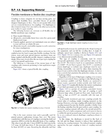
Fig 4.8.2 Single diaphragm spacer coupling (Courtesy of Lucas
to wear and have an infinite life span. Aerospace)
All provide smooth, predictable response to cyclic correction
for minor misalignment.
will significantly increase the axial load on the thrust bearings of
It should be noted that none of the above comments can be the equipment, and can fail the coupling discs. A single di-
applied across the board to gear type flexible couplings. For this aphragm, spacer type coupling is shown in Figures 4.8.1 and
reason, more and more special purpose machinery trains are 4.8.2. Figure 4.8.1 is a cutaway view and Figure 4.8.2 presents
being supplied with flexible metallic element couplings in their a two dimensional assembly drawing.
design. Many users do not allow the use of gear type coupling for This type of coupling is commonly used for critical
critical (un-spared) applications. (un-spared) applications where axial end float values are less
The following is a discussion of the various types of ‘dry’ than 0.125". This limit is based on an approximate axial float
couplings with comments pertaining to their application ranges of 0.062". If end float is greater than 0.125", a convoluted
and limitations. (wavy) diaphragm or multiple type diaphragm must be used.
Figure 4.8.1 shows a typical flexible disc coupling. During disassembly, care must be taken when removing the
spacer to not scratch or dent the diaphragm element. A dent or
even a scratch that penetrates the protective coating can cause
a diaphragm failure.
Regardless of the type of diaphragm couplings, it is common
practice to ‘pre-stretch’ these couplings to take full advantage of
the maximum available end float. Readers are cautioned to
always require equipment vendors provide axial shaft move-
ment. Figure 4.8.4 graphically displays the various combinations
of end shaft movement and the calculation method.
Figure 4.8.5 is a picture of a multiple, convoluted (wavy)
diaphragm spacer coupling. This type of coupling is used
whenever large values of axial end float exist. Axial end float
values as high as 0.875" are attainable with this type of
coupling.
As previously mentioned, gear type couplings provide the
lowest value of overhung weight (coupling moment) on the
bearing. However, a dry type coupling will usually have a higher
coupling moment because the flexible assembly is farther from
the bearing centerline than the gear teeth in a gear coupling. An
Fig 4.8.1 Flexible disc spacer coupling (Courtesy of Rexnord)
excessive coupling moment will reduce the second natural fre-
quency (N c2 ) of a turbo-compressor and could move it close to
or within the operating speed range. A solution in these cases can
This is the most common type and is generally used for be to use a reduced moment diaphragm coupling as shown in
general purpose applications (pumps, fans, etc). The major Figure 4.8.6.
consideration with this type of coupling is assuring the shaft end In this design, the diaphragm is moved to the back of
separation (BSE) is within the allowable limits of the couplings. the hub and the flange diameter is reduced thus significantly
This value is typically only 1.5mm (0.060") for shaft sizes in the reducing the coupling moment. The reduced moment coupling
1-2" range. At shaft sizes above 4", the maximum end float can approaches the gear coupling in term of coupling moment
be 6mm (0.150") or more. Exceeding the allowable end float value.
255