
Page 338 - Subyek Teknik Mesin - Forsthoffers Best Practice Handbook for Rotating Machinery by William E Forsthoffer
P. 338
Steam Turbine Best Practices Best Practice 5 .14
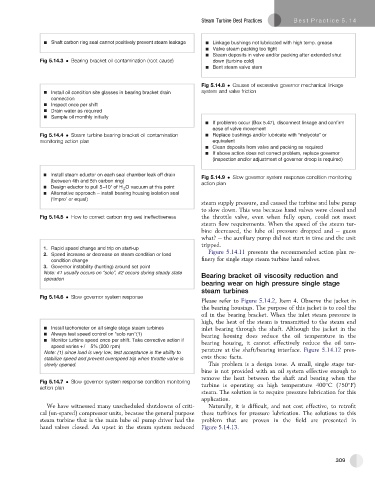
Shaft carbon ring seal cannot positively prevent steam leakage Linkage bushings not lubricated with high temp. grease
Valve steam packing too tight
Steam deposits in valve and/or packing after extended shut
Fig 5.14.3 Bearing bracket oil contamination (root cause) down (turbine cold)
Bent steam valve stem
Fig 5.14.8 Causes of excessive governor mechanical linkage
Install oil condition site glasses in bearing bracket drain system and valve friction
connection
Inspect once per shift
Drain water as required
Sample oil monthly initially
If problems occur (Box 5.47), disconnect linkage and confirm
ease of valve movement
Fig 5.14.4 Steam turbine bearing bracket oil contamination Replace bushings and/or lubricate with “molycote” or
monitoring action plan equivalent
Clean deposits from valve and packing as required
If above action does not correct problem, replace governor
(inspection and/or adjustment of governor droop is required)
Install steam eductor on each seal chamber leak off drain
Fig 5.14.9 Slow governor system response condition monitoring
(between 4th and 5th carbon ring)
action plan
Design eductor to pull 5–10'' of H 2 O vacuum at this point
Alternative approach – install bearing housing isolation seal
(‘Impro’ or equal)
steam supply pressure, and caused the turbine and lube pump
to slow down. This was because hand valves were closed and
Fig 5.14.5 How to correct carbon ring seal ineffectiveness the throttle valve, even when fully open, could not meet
steam flow requirements. When the speed of the steam tur-
bine decreased, the lube oil pressure dropped and e guess
what? e the auxiliary pump did not start in time and the unit
tripped.
1. Rapid speed change and trip on start-up
2. Speed increase or decrease on steam condition or load Figure 5.14.11 presents the recommended action plan re-
condition change finery for single stage steam turbine hand valves.
3. Governor instability (hunting) around set point
Note: #1 usually occurs on “solo”, #2 occurs during steady state Bearing bracket oil viscosity reduction and
operation
bearing wear on high pressure single stage
steam turbines
Fig 5.14.6 Slow governor system response
Please refer to Figure 5.14.2, Item 4. Observe the jacket in
the bearing housings. The purpose of this jacket is to cool the
oil in the bearing bracket. When the inlet steam pressure is
high, the heat of the steam is transmitted to the steam end
Install tachometer on all single stage steam turbines inlet bearing through the shaft. Although the jacket in the
Always test speed control on “solo run” (1) bearing housing does reduce the oil temperature in the
Monitor turbine speed once per shift. Take corrective action if bearing housing, it cannot effectively reduce the oil tem-
speed varies + / 5% (200 rpm)
Note: (1) since load is very low, test acceptance is the ability to perature at the shaft/bearing interface. Figure 5.14.12 pres-
stabilize speed and prevent overspeed trip when throttle valve is ents these facts.
slowly opened. This problem is a design issue. A small, single stage tur-
bine is not provided with an oil system effective enough to
remove the heat between the shaft and bearing when the
Fig 5.14.7 Slow governor system response condition monitoring turbine is operating on high temperature 400 C (750 F)
action plan
steam. The solution is to require pressure lubrication for this
application.
We have witnessed many unscheduled shutdowns of criti- Naturally, it is difficult, and not cost effective, to retrofit
cal (un-spared) compressor units, because the general purpose these turbines for pressure lubrication. The solutions to this
steam turbine that is the main lube oil pump driver had the problem that are proven in the field are presented in
hand valves closed. An upset in the steam system reduced Figure 5.14.13.
309