
Page 335 - Subyek Teknik Mesin - Forsthoffers Best Practice Handbook for Rotating Machinery by William E Forsthoffer
P. 335
Steam Turbine Best Practices Best Practice 5 .14
Best
Best Practice 5.14Practice 5.14
Install a low pressure steam seal eductor and oil condition Lessons Learned
monitoring bottles on single stage turbines to prevent and Failure to design single stage turbine steam seal systems
monitor bearing oil contamination. for vacuum systems and bearing bracket oil condition
A common reliability issue with single stage steam turbines is the monitoring bottles has resulted in frequent turbine shut-
undetected steam seal wear and entrance of condensate into the small
downs for seal and oil changes and catastrophic bearing
volume bearing housings.
failure and fires (resulting from ‘red hot’ bearing housings).
Steam seal wear will rapidly displace bearing oil with condensate
causing Babbitt-lined, sleeve bearing wear with potentially dangerous
consequences. Benchmarks
This best practice has been used since the mid 1990s for recom-
Installation of a low pressure steam eductor and associated piping
mended field modifications and project requirements. Major oil com-
with a vacuum gauge from each seal leak off port will function in the same
panies have adapted this best practice to produce steam seal MTBFs
manner as special purpose steam turbine seal systems (see BP 5. 8), and
positively prevent the entry of condensate into the bearing housing. in excess of 100 months.
Installation of oil condition monitoring bottles at the bottom of each
bearing bracket will allow operations to monitor bearing oil condition
by observing water accumulated in the bottom of the bottle.
B.P. 5.14. Supporting Material system linkage during start-up, and during normal operation
when steam conditions change. It appears as if the governor is
not responding because speed will not be controlled when it
Single stage turbine guidelines should. Typical examples are:
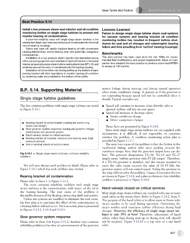
The five common problems with single stage turbines are noted - Speed will continue to increase when throttle valve is
in Figure 5.14.1. opened; turbine will trip on over speed
- Speed will increase or decrease when:
- Steam conditions change
- Driver equipment changes
Bearing bracket oil contamination (inadequate carbon ring
steam seal design) These facts are presented in Figure 5.14.6.
Slow governor system response (inadequate governor linkage Since most single stage steam turbines are not supplied with
maintenance and governor power) tachometers, it is difficult, if not impossible, to condition
Hand valve(s) closed on critical services
Bearing bracket oil viscosity reduction and bearing wear (high monitor this problem. A condition monitoring action plan is
pressure service) provided in Figure 5.14.7.
Use of sentinal valves on turbine cases The usual root cause of the problem is that the friction in the
mechanical linkage and/or valve stem packing exceeds the
maximum torque force that the governor output lever can de-
Fig 5.14.1 Single stage steam turbines: common reliability liver. The governor designations TG-10, TG-13 and TG-17
problems
simply mean ‘turbine governor with FT-LB torque’. Therefore,
if a TG-10 governor is installed, and the torque required to
We will now discuss each problem in detail. Please refer to move the valve steam exceeds the value of 10 FT-LBs, the
Figure 5.14.2 which has each problem area circled. governor system will not control speed. Taking the governor to
the shop will not solve the problem. Causes of excessive friction
Bearing bracket oil contamination are shown in Figure 5.14.8, and a plan to eliminate this reliability
problem is presented in Figure 5.14.9.
Please refer to Item 1 in Figure 5.14.2.
The most common reliability problem with single stage
steam turbines is the contamination, with water, of the oil in Hand valve(s) closed on critical services
thebearing housing. Theroot cause of theproblem is Most single stage steam turbines are supplied with one or more
the ineffectiveness of the floating carbon ring shaft seal system. hand valves in the steam chest. Refer to Figure 5.14.2, Item 3.
Unless site systems are modified to eliminate the root cause, The purpose of the hand valves is to allow more or fewer inlet
the best plan is to minimize the effect of the contamination so steam nozzles to be used during operation. Optimizing the
a bearing failure will not occur. Such an action plan is presented steam nozzles used maintains turbine efficiency during load
in Figures 5.14.3, 5.14.4 and 5.14.5. changes. However, the efficiency of single stage steam tur-
bines is only 35% at best! Therefore, adjustment of hand
Slow governor system response valves, other than during start-up or during slow roll, should
Please refer to Item 2 in Figure 5.14.2. Another very common not be required. Figure 5.14.10 is atop view of aonehand
reliability problem is the slow or non-movement of the governor valve.
307