
Page 330 - Subyek Teknik Mesin - Forsthoffers Best Practice Handbook for Rotating Machinery by William E Forsthoffer
P. 330
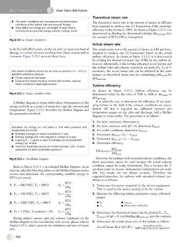
Be st Practice 5 .13          Steam Turbine Best Practices
                                                            Theoretical steam rate
           The steam conditions are the pressure and temperature  The theoretical steam rate is the amount of steam, in LBS per
           conditions at the turbine inlet and exhaust flanges  hour required to produce one (1) horsepower if the isentropic
           They define the energy per unit weight of vapor that is
           converted from potential energy to kinetic energy (work)  efficiency of the turbine is 100%. As shown in Figure 5.13.5,itis
                                                            determined by dividing the theoretical enthalpy Dh isentropic into
                                                            the amount of BTUs/HR in horsepower.
       Fig 5.13.1   Steam conditions
                                                            Actual steam rate
       to do this will affect power produced, and can cause mechanical  The actual steam rate is the amount of steam, in LBS per hour,
       damage to turbine internals resulting from blade erosion and/or  required to produce one (1) horsepower based on the actual
       corrosion. Figure 5.13.2 presents these facts.       turbine efficiency. As shown in Figure 5.13.5, it is determined
                                                            by dividing the theoretical steam rate (TSR) by the turbine ef-
                                                            ficiency. Alternately, if the turbine efficiency is not known and
                                                            the turbine inlet and exhaust conditions are given (P 2 ,T 2 or %
        Inlet steam conditions should be as close as possible (+ /  5%) to  moisture), the actual steam rate can be obtained in the same
        specified conditions because:                        manner as theoretical steam rate but substituting DH actual for
           Power output will decrease                       DH isentropic .
           Exhaust end steam moisture content will increase, causing
           blade, nozzle and diaphragm erosion
                                                            Turbine efficiency
                                                            As shown in Figure 5.13.5, turbine efficiency can be
       Fig 5.13.2   Steam condition limits                  determined either by the ratio of TSR to ASR or Dh actual to
                                                            DH isentropic .
                                                              It is relatively easy to determine the efficiency of any oper-
          A Mollier diagram or steam tables allow determination of the
       energy available in a pound of steam for a specific pressure and  ating turbine in the field if the exhaust conditions are super-
       temperature. Figure 5.13.3 describes the Mollier diagram and  heated. All that is required are calibrated pressure and
       the parameters involved.                             temperature gauges on the inlet and discharge, and a Mollier
                                                            diagram or steam tables. The procedure is as follows:

                                                            1. For inlet conditions, determine h 1
        Describes the energy per unit mass of fluid when pressure and  2. For inlet condition with DS ¼ 0, determine h 2ideal
        temperature are known.                              3. For outlet conditions, determine h 2actual
           Enthalpy (energy/unit mass) is plotted on Y axis  4. Determine Dh ideal ¼ h 1   h 2ideal
           Entropy (energy/unit mass degree) is plotted on X axis
                                                            5. Determine Dh actual ¼ h 1   h 2actual
           Locating P 1 ,T 1 gives a value of enthalpy (H) horizontal and
           entropy (S) vertical                             6. Determine efficiency
           Isentropic expansion occurs at constant entropy ( S = 0) and
           represents an ideal (reversible) expansion                   DH actual
                                                              Efficiency ¼
                                                                        DH ideal
       Fig 5.13.3   The Mollier Diagram                       However, for turbines with saturated exhaust conditions, the
                                                            above procedure cannot be used because the actual exhaust
                                                            condition cannot be easily determined. This is because the %
          Refer to Figure 5.13.4 e an enlarged Mollier Diagram. As an
       exercise, plot the following values on the Mollier Diagram in this  moisture must be known. Instruments (calorimeters) are avail-
       section and determine the corresponding available energy in  able, but results are not always accurate. Therefore the
       BTUs per pound.                                      suggested procedure for turbines with saturated exhaust con-
                                                            ditions is as follows:
                                           BTU
       1. P 1 ¼ 600 PSIG, T 1 ¼ 800 F  h 1 ¼                1. Determine the power required by the driven equipment.

                                           LB M
                                                               This is equal to the power produced by the turbine.
                                           BTU
       2. P 2 ¼ 150 PSIG, T 2 ¼ 580 F  h 2 ¼                2. Measure the following turbine parameters using calibrated

                                           LB M
                                                               gauges:
                                           BTU

       3. P 1 ¼ 1500 PSIG, T 1 ¼ 900 F  h 1 ¼                  - P in         - P exhaust
                                           LB M                               - Steam flow (in lbs/hr)
                                                               - T in
                                           BTU
       4. P 2 ¼ 2 PSIG, % moisture ¼ 9%  h 2 ¼              3. Determine the theoretical steam rate by plotting P in ,T in ,
                                           LB M
                                                               P exhaust @ DS ¼ 0, and dividing Dh isentropic into the constant.
          Having plotted various inlet and exhaust conditions on the
       Mollier diagram to become familiar with its use, please refer to  4. Determine the actual steam rate of the turbine as follows:
       Figure 5.13.5, which presents the definitions and uses of steam                       Steam Flow ðlb=hrÞ
                                                               Actual Steam Rate (A.S.R.) ¼  BHP required by driven equipment
       rate.
           302