
Page 399 - Subyek Teknik Mesin - Forsthoffers Best Practice Handbook for Rotating Machinery by William E Forsthoffer
P. 399
Be st Practice 7 .7 Lube, Seal and Control Oil System Best Practices
displacement and centrifugal pump will be selected and
compared.
The following data is available:
Pumped fluid data
Type e light mineral oil e 150 SSU @ 100 F
Conditions Minimum Normal Maximum
Pressure (PSIG) 0.63 0.75 1.22
Temperature ( F) 40 F 150 160 F
Specific gravity 0.85 0.85 0.85
Viscosity (SSU) 1,000 60 57
Vapor pressure (PSIA) 0.001 0.001 0.001
Pump suction and discharge pressures
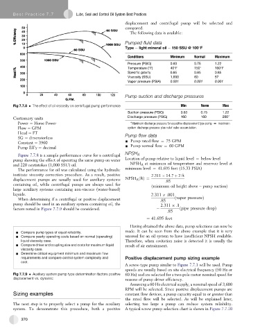
Fig 7.7.8 The effect of oil viscosity on centrifugal pump performance Min Norm Max
Suction pressure (PSIG) 0.63 0.75 1.22
Customery units Discharge pressure (PSIG) 160 160 200 )
Power ¼ Horse Power ) Maximum discharge pressure for a positive displacement type pump [ maximum
Flow ¼ GPM system discharge pressure plus relief valve accumulation.
Head ¼ FT Pump flow data
SG ¼ dimensionless
Constant ¼ 3960 - Pump rated flow ¼ 75 GPM
Pump Eff’y ¼ decimal - Pump normal flow ¼ 60 GPM
Figure 7.7.8 is a sample performance curve for a centrifugal NPSH A
pump showing the effect of operating the same pump on water Location of pump relative to liquid level ¼ below level
and 220 centistokes (1,000 SSU) oil. NPSH A at minimum oil temperature and reservoir level at
The performance for oil was calculated using the hydraulic minimum level ¼ 41.695 feet (15.33 PSIA)
institute viscosity correction procedure. As a result, positive 2:311 14:7 þ 2ft
displacement pumps are usually used for auxiliary systems NPSH A ðftÞ¼ :85
containing oil, while centrifugal pumps are always used for
ðminimum oil height above pump suctionÞ
large auxiliary systems containing non-viscous (water-based)
liquids. 2:311 :001
When determining if a centrifugal or positive displacement :85 ðvapor pressureÞ
pump should be used in an auxiliary system containing oil, the 2:311 :1
factors noted in Figure 7.7.9 should be considered. ðpipe pressure dropÞ
:85
¼ 41:695 feet
Having obtained the above data, pump selections can now be
made. It can be seen from the above example that it is very
Compare pump types of equal reliability.
Compare yearly operating costs based on normal (operating) unusual for an oil system to have insufficient NPSH available.
liquid viscosity case. Therefore, when cavitation noise is detected it is usually the
Compare driver and coupling size and costs for maximum liquid result of air entrainment.
viscosity case.
Determine critical equipment minimum and maximum flow
requirements and compare control system complexity and Positive displacement pump sizing example
cost.
A screw-type pump similar to Figure 7.7.1 will be used. Pump
speeds are usually based on site electrical frequency (50 Hz or
Fig 7.7.9 Auxiliary system pump type determination factors positive 60 Hz) and are selected for a two-pole motor nominal speed for
displacement vs. dynamic reasons of pump driver efficiency.
Assuming a 60 Hz electrical supply, a nominal speed of 3,600
RPM will be selected. Since positive displacement pumps are
Sizing examples constant flow devices, a pump capacity equal to or greater than
the rated flow will be selected. As will be explained later,
The next step is to properly select a pump for the auxiliary selecting too large a pump can reduce system reliability.
system. To demonstrate this procedure, both a positive A typical screw pump selection chart is shown in Figure 7.7.10
370