
Page 402 - Subyek Teknik Mesin - Forsthoffers Best Practice Handbook for Rotating Machinery by William E Forsthoffer
P. 402
Lube, Seal and Control Oil System Best Practices Be st Practice 7.7
S y m o t p m A o i t c n
1. Pump noisy, excessive wear A. Confirm NPSH A > NPSH R
(since first day of operation) B. Calculate NPSH A
C. Obtain NPSH R from pump
vendor for actual operating
conditions
If NPSH A > NPSH R , proceed to
Step 2
If NPSH R > NPSH A :
Raise liquid level to correct
problem
Or
Lower pump relative to liquid
level
Or
Change to pump with
acceptable NPSH R
2. Pump noisy, possible pump A. Tape or coat pump suction
wear (problem occurs piping with heavy oil if sound
intermittently or has recently stops, correct suction piping
occurred) leak.
B. Inspect pump seal at first
opportunity for signs of wear
in both primary and
secondary (shaft sleeve ‘O’
ring or packing) seal
C. Check reservoir for entrained
air or gasses
Caution – obtain work permit
prior to obtaining sample.
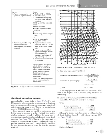
If gasses or air are in liquid Fig 7.7.13 Hydraulic institute viscosity correction factors
(cloudy sample – not clear),
correct problem by proper 1. Determine ‘uncorrected’ rated point
degassing, reservoir
modification or drain pipe 2:311 ðP 2 P 1 Þ
T:D:H: ðTotal differential headÞ ¼
modification. Specific gravity
NOTE: This is a difficult problem )
and can require extensive From data on previous page ¼ 2:311 198:8
modifications. :85
¼ 540:5 feet
Fig 7.7.12 Pump cavitation and aeration checklist Q rated ¼ 75 GPM
)
A discharge pressure of 200 PSIG was used since a relief
valve is not required with a dynamic pump because it is
self-limiting.
Centrifugal pump sizing example 2. Determine the viscosity corrected head and rated flow
A centrifugal type pump similar to Figure 7.7.3 will be used. required for the maximum viscosity to be pumped
Data available is the same as the previous pump application as Given:
noted on previous page. The same comments apply as previously Q rated uncorrected ¼ 75 GPM
stated concerning pump speed. Therefore a nominal pump Head rated uncorrected ¼ 540:5 feet
speed of 3,600 RPM has been selected.
Maximum pumped viscosity ¼ 1;000 SSU
Since a dynamic pump is a variable capacity device, a se-
lection curve, as opposed to a chart (utilized for a positive Referring to viscosity correction factors as published by the
displacement pump) is used. In addition, the pump must be Hydraulic Institute standards e 12th edition, copyright 1969
oversized to account for the effects of oil viscosity as previously (see Figure 7.7.13).
explained (see Figure 7.7.8). Therefore, the pump must be Q correction factor ¼ 0:80
selected to produce the performance requirements noted on Head correction factor ¼ 1:00
previous page at the ‘worst case’ e highest viscosity conditions. Efficiency correction factor ¼ 0:5
In order to select the proper pump the following steps are
required: For the rated point.
373