
Page 405 - Subyek Teknik Mesin - Forsthoffers Best Practice Handbook for Rotating Machinery by William E Forsthoffer
P. 405
Be st Practice 7 .9 Lube, Seal and Control Oil System Best Practices
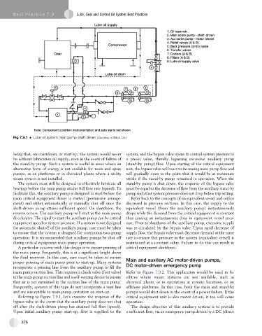
Fig 7.9.1 Lube oil system main pump shaft-driven (Courtesy of Elliott Co.)
being that, on coastdown, or start-up, the system would never system, and the bypass valve opens to control system pressure to
be without lubrication oil supply, even in the event of failure of a preset value, thereby bypassing excessive auxiliary pump
the stand-by pump. Such a system is useful in areas where an (stand-by pump) flow. Upon starting of the critical equipment
alternative form of energy is not available for main and spare unit, the bypass valve will react to increasing main pump flow and
pumps, as on platforms or in chemical plants where a utility will gradually open to the point that it would be at maximum
steam system is not installed. stroke if the stand-by pump remained in operation. When the
The system must still be designed to effectively lubricate all stand-by pump is shut down, the response of the bypass valve
bearings before the main pump attains full flow rate (speed). To must be equal to the decrease of flow from the auxiliary stand-by
facilitate this, the auxiliary pump is designed to start before the pump such that system pressure does not drop below trip setting.
main critical equipment driver is started (permissive arrange- Refer back to the concepts of an equivalent vessel and orifice
ment) and either automatically or manually shut off once the discussed in previous sections. In this case, the supply to the
shaft-driven pump attains sufficient speed. On shutdown, the equivalent vessel (from the auxiliary pump) instantaneously
reverse occurs. The auxiliary pump will start as the main pump drops while the demand from the critical equipment is constant
decelerates. The signal to start the auxiliary pump can be critical thus causing an instantaneous drop in equipment vessel pres-
equipment speed or system pressure. If a system is not designed sure. Prior to shutdown of the auxiliary pump, excessive supply
for automatic shutoff of the auxiliary pump, care must be taken was re-circulated by the bypass valve. Upon rapid decrease of
to ensure that the system is designed for continuous two-pump supply flow, the bypass valve must decrease demand at the same
operation. It is recommended that auxiliary pumps be shut off rate to ensure that pressure in the system (equivalent vessel) is
during critical equipment main pump operation. maintained at a constant value. Failure to do this can result in
A particular concern with this design is to ensure priming of critical equipment shutdown.
the main pump. Frequently, this is at a significant height above
the fluid reservoir. In this case, care must be taken to ensure
proper priming of main pump prior to start-up. Many systems Main and auxiliary AC motor-driven pumps,
incorporate a priming line from the auxiliary pump to fill the DC motor-driven emergency pump
main pump suction line. This requires a check valve (foot valve) Refer to Figure 7.9.2. This application would be used in fa-
in the main pump suction line and a self-venting device to ensure cilities where steam systems are not available, such as
that air is not entrained in the suction line of the main pump. chemical plants, or in operations at remote locations, or on
Frequently, systems of this type do not incorporate a vent line offshore platforms. In this case, both the main and stand-by
and are susceptible to main pump cavitation on start-up. pumps would shut down in the event of a power failure. If the
Referring to Figure 7.9.1,let’s examine the response of the critical equipmentunitisalsomotor driven,ittoowill cease
bypass valve in the event that the auxiliary pump does not shut operation.
off after the shaft-driven pump has attained full flow (speed). The design objective of this auxiliary system is to provide
Upon initial auxiliary pump start-up, flow is supplied to the a sufficient flow, via an emergency pump driven by a DC (direct
376