
Page 408 - Subyek Teknik Mesin - Forsthoffers Best Practice Handbook for Rotating Machinery by William E Forsthoffer
P. 408
Lube, Seal and Control Oil System Best Practices Be st Practice 7.9
will supply sufficient lube oil for rundown (refer to
Figure 7.9.6).
The function of the tank is to provide oil to all bearings at
a lower pressure than normal, but still sufficient to preclude
bearing damage during emergency shutdown. In this case, the
tank will drain when both main and auxiliary pumps cease to
function. An important consideration is the material of the
rundown tank, since it represents a large vessel downstream of
the filter in the system. Any rust scale or corrosion present in
this tank will go directly into the bearings on shutdown and
could causeasignificant problem. Rundown tanks should also
be sized to provide sufficient flow for the entire coastdown
period. The calculation of the equipment coastdown time must
include process system information. The lower the system
Fig 7.9.5 Non-identical pumps with stable head curves
pressure (resistance) during the coastdown period, the longer
the equipment will continue to turn. The vendor and user must
An important consideration in this system is that both main coordinate closely regarding the rundown tank sizing. It is
and auxiliary pumps operate at essentially the same speed and recommended that a small amount of flow be continuously
have essentially the same characteristic curves. (This would not circulated through the rundown tank to prevent sediment ac-
be the case if one pump had excessively worn internals.) cumulation and maintain operating viscosity (in cold regions).
Therefore, the total output flow of the pumps would be a result This is accomplished by installing a return line from the tank to
of the combined curve of the pump output. Refer to the oil drain line that incorporates an orifice to regulate flow
Figure 7.9.5 for a view of the combined effect of both pumps (approximately 8 LPM [2 GPM]).
operating in parallel. From this example, the importance of It is strongly recommended for lube systems with rundown
ensuring correct similar characteristics of both main and aux- tanks or emergency pumps that in the case of equipment shut-
iliary pumps in systems incorporating dynamic pumps can be down, even though equipment is furnished with rundown tanks
seen. If one pump is steam turbine-driven, it is important to and emergency pumps, bearings should be checked for wear upon
periodically check speed, and correct the turbine governor coastdown. Failure to do so could result in catastrophic damage to
setting if necessary. The motor and turbine speeds should be the equipment if bearings were failed at shutdown. Additionally,
the same. in systems employing gears, gear box inspection covers should be
removed and the gear mesh checked since spray elements, if
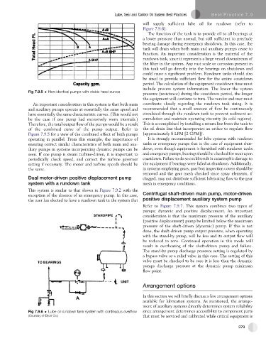
Dual motor-driven positive displacement pump clogged, may not distribute sufficient lubricating flow to the gear
system with a rundown tank mesh in emergency conditions.
This system is similar to that shown in Figure 7.9.2 with the
exception of the absence of an emergency pump. In this case, Centrifugal shaft-driven main pump, motor-driven
the user has elected to have a rundown tank in the system that positive displacement auxiliary system pump
Refer to Figure 7.9.7.Thissystemcombinestwo typesof
pumps; dynamic and positive displacement. An important
consideration is that the maximum pressure of the auxiliary
(positive displacement) pump be limited below the maximum
pressure of the shaft-driven (dynamic) pump. If this is not
done, the shaft-driven pump output pressure, when operating
with the stand-by pump, will be less and its output flow will
be reduced to zero. Continued operation in this mode will
result in overheating of the shaft-driven pump and failure.
The stand-by pump discharge pressure setting is regulated by
a bypass valve or a relief valve in this case. The setting of this
valve must be checked to be sure it is less than the dynamic
pumps discharge pressure at the dynamic pump minimum
flow point.
Arrangement options
In this section we will briefly discuss a few arrangement options
available for lubrication systems. As mentioned, the arrange-
ment of auxiliary systems directly determines system reliability
Fig 7.9.6 Lube oil rundown tank system with continuous overflow since arrangement determines accessibility to component parts
(Courtesy of Elliott Co.) that must be serviced and calibrated while critical equipment is
379