
Page 412 - Subyek Teknik Mesin - Forsthoffers Best Practice Handbook for Rotating Machinery by William E Forsthoffer
P. 412
Lube, Seal and Control Oil System Best Practices Best Practice 7 .11
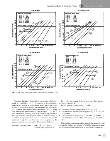
Fig 7.11.2 Relief valve sizing chart (Courtesy of Fulflow Specialties Co. Inc.)
Experience has shown that a sliding, piston-type, relief valve, Relief valve overpressure is the valve pressure drop necessary
which is a modulating device, as opposed to a spring-loaded to pass full pump flow.
poppet valve, which is an on-off device, meets the requirements For the present example using a 2" valve:
of stability and positive shutoff for liquid auxiliary system ser-
vice. A typical relief valve is shown in Figure 7.11.1. A sizing 1. Maximum pump discharge pressure ¼ 200 PSIG
chart for this type of relief valve is shown in Figure 7.11.2. Relief 2. Relief valve set pressure (cracking pressure) ¼ 1.1 200
valve set pressure is usually set 10% above the pump maximum ¼ 220 PSIG
discharge pressure. However, the maximum pressure ratings of 3. Maximum system overpressure ¼ 220 PSIG þ 25 PSIG ¼
all system components must also be considered. Given the 245 PSIG (from Figure 7.11.2 for Y spring and 86 GPM
maximum pump flow and the relief valve set pressure, the flow)
maximum system pressure can be determined as follows:
Note that the overpressure values are sensitive to viscosity, and
Maximum system pressure ¼ relief valve set pressure can only be used up to a viscosity of 500 SSU. Above this value,
þ relief valve overpressure: the overpressure can be estimated to vary by the relationship:
383