
Page 414 - Subyek Teknik Mesin - Forsthoffers Best Practice Handbook for Rotating Machinery by William E Forsthoffer
P. 414
Lube, Seal and Control Oil System Best Practices Best Practice 7 .13
B.P. 7.13. Supporting Material components must have response times of the order of milli-
seconds. When one considers the function of an auxiliary system
Referring to the general definition of an auxiliary system which and the fact that the slowest of critical equipment units operate
at approximately 60 revolutions per second (3,600 RPM), the
is ‘to continuously supply cool, clean fluid to each specified point
at the required pressure, temperature and flow rate’, we can see necessity of rapid system response time can be appreciated. If
that the controls and instruments play a major role in the re- the controls cannot respond to a transient response, the in-
liability of auxiliary systems. The function of the controls and strumentation and the critical equipment shutdown system
instrumentation is to continuously supply fluid to each specified (circuit breaker, steam turbine trip valve system, etc.) must
point at the required pressure, temperature and flow rate. While operate on demand to stop equipment operation. If the system
it is true that pumps and coolers must be present, system con- controls and instrumentation do not have sufficient response
trols modify the operational characteristics of these components times, a system liquid supply source (accumulator) is required
to achieve the desired results. In addition, system in- to provide flow during transient conditions. Using our system as
strumentation initiates transient system response, continuously an example, 60 GPM e or one gallon per second e are supplied
monitors operation and shuts down critical equipment in the to the unit. Suppose the main pump trips, and the normal flow
event of an auxiliary system malfunction. In this section, we will to the equipment is not reached for three seconds (until the
examine important concepts that are at the heart of auxiliary stand-by pump is at full speed and flow rate). An accumulator
system reliability, define the function of major control and in- with a liquid capacity of three gallons would enable the system
strumentation components and discuss items that can signifi- to function normally during the upset since it would supply the
cantly reduce auxiliary system reliability. required flow of one gallon per second. Note an accumulator size
greater than three gallons would be required. This will be cov-
ered separately.
Types
Types of major auxiliary system controls and instrumentation Concepts
are outlined in Figure 7.13.1. Note that types are defined by
function. As an example, a positive displacement pump system The use of concepts can be helpful in understanding the func-
flow control consists of a pressure control valve that bypasses tion of auxiliary system components and systems. In this section
excess flow from the pump back to the system reservoir to we will discuss:
maintain a set system pressure. The function of this component,
however, is to continuously supply the required flow of fluid to - An equivalent orifice
the system under varying system pressure drops and critical - Sub-systems
equipment component conditions (worn bearing, seal, etc.). - An equivalent vessel
- Control valve liquid coefficient e C v
- A flow meter in every system
Instrumentation monitor and
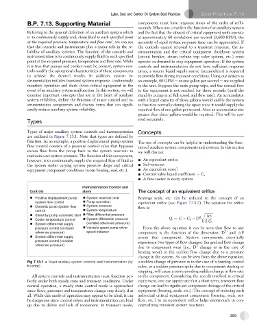
Controls alarm The concept of an equivalent orifice
Positive displacement pump System reservoir level Bearings seals, etc. can be reduced to the concept of an
system flow control Pump operation equivalent orifice (see Figure 7.13.2). The equation for orifice
Dynamic pump system flow System pressure flow is:
control System temperature
Stand-by pump automatic start Filter differential pressure 2 r ffiffiffiffiffiffiffiffiffiffi
Dp
Cooler temperature control System differential pressure Q ¼ C C D S:G:
f
System differential supply (variable reference pressure)
pressure control (constant Variable speed pump driver From the above equation it can be seen that flow to any
2
reference pressure) speed indicator component is the function of the dimension ‘D ’ and 6P
System differential supply across that component. System components essentially
pressure control (variable
experience two types of flow changes; the gradual flow change
reference pressure) 2
due to component wear (i.e., D change as in the case of
bearing wear) or the sudden flow change due to a pressure
change in the system. As can be seen from the above equation,
Fig 7.13.1 Major auxiliary system controls and instrumentation (by a sudden change of pressure as in the case of a hunting control
function) valve, or a sudden pressure spike due to component starting or
stopping, will cause a corresponding sudden change in flow rate
All system controls and instrumentation must function per- to the component. Considering the speeds involved in critical
fectly under both steady state and transient conditions. Under equipment, one can appreciate that a short term, transient flow
normal operation, a steady state control mode is approached change can lead to significant component damage of the critical
since flows, pressures and temperatures change very slowly if at equipment (bearing, seals, etc.). The concept of reducing each
all. While this mode of operation may appear to be ideal, it can individual critical equipment component (bearing, seals, ori-
be dangerous since control valves and instrumentation can bind fices, etc.) to an equivalent orifice helps enormously in con-
up due to debris and lack of movement. In transient mode, ceptualizing transient system reactions.
385