
Page 416 - Subyek Teknik Mesin - Forsthoffers Best Practice Handbook for Rotating Machinery by William E Forsthoffer
P. 416
Lube, Seal and Control Oil System Best Practices Best Practice 7 .13
When supply flow equals exit flow, the pressure in any We can see by referring back to ‘the concept of an equivalent
equivalent vessel remains constant. If supply flow is less than orifice’ that this equation is similar to that of an orifice. Natu-
exit flow, the pressure reduces rapidly. The function of an ac- rally, the only difference is that a valve is a variable orifice.
cumulator can be easily understood by using this equivalent Valves are sized using this concept of C v (valve coefficient).
vessel concept. If a vessel is installed downstream of the Each valve has a maximum C v . Depending on the type of in-
equivalent vessel in Figure 7.13.3, during the period of reduced ternal valve design, seats, plugs, and body, a valve will exhibit
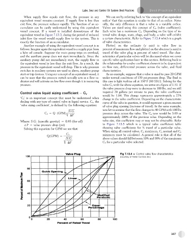
inlet flow the vessel would supply flow to the system. This is a certain characteristic. Refer to Figure 7.13.4 which is a graph
exactly the function of an accumulator. of valve characteristics.
Another example of using the equivalent vessel concept is as Plotted on the ordinate (y axis) is valve flow in
follows: Imagine again the equivalent vessel is a supply pipe from percent of maximum flow and plotted on the abscissa (x axis) is
a lube oil console. Suppose the main pump trips on overload, travel of the valve plug in percent of rated travel. The char-
and the auxiliary pump does not start immediately. Since the acteristics of particular valves will be discussed when we cover
auxiliary pump did not immediately start, the supply flow to specific valve application later in this section. Referring back to
the equivalent vessel is less than the exit flow. As a result, the the relationship for a valve coefficient shows it to be dependent
pressure in the equivalent vessel will drop. This is why pressure on flow rate, differential pressure across the valve, and fluid
switches in auxiliary systems are used as alarm, auxiliary pump characteristics.
start or trip devices. Using our concept of an equivalent vessel, it As an example, suppose that a valve is sized to pass 20 GPM
can be seen that the pressure switch actually acts as a flow in- under normal conditions of 150 psi pressure drop. The fluid in
dicator and will activate on low flow even though it is measuring this case is light turbine oil at 150 F (60 SSU). Solving for the
pressure. valve C v with the above equation, we arrive at a figure of 1.51. If
the valve pressure drop were to decrease to 100 lbs, and we still
required 20 gallons per minute to pass, the valve coefficient
Control valve liquid sizing coefficient e C v
would be 1.84. This change represents approximately a 22%
‘C v ’ is an important concept that must be understood when change in the valve coefficient. Depending on the characteristic
dealing with any type of control valve in liquid service. C v , the curve of the valve in question, it would represent a given amount
‘valve sizing coefficient’,is defined by the following equation: of valve plug opening (increase of travel). In the same example,
r ffiffiffiffiffiffiffiffiffiffi now let us assume that the flow changes to 40 GPM with 100 lbs
S:G:
C v ¼ Q ðGPMÞ pressure drop across the valve. The C v now would be 3.69 or
DP
approximately 200% of the previous value. Depending on the
Where: S.G. (specific gravity) ¼ 0.85 (for oil) valve size, this coefficient may or may not be obtainable. Refer
6P ¼ value pressure drop (psi) to Figure 7.13.5 which is a typical valve coefficient table
showing valve coefficients for % travel of a particular valve.
Solving this equation for GPM we see that:
When sizing all control valves, C v maximum, C v normal and C v
C v minimum must be calculated. A general rule is that all of the
QðGPMÞ¼ r ffiffiffiffiffiffiffiffiffiffi
S:G: above values should fall between 10% and 90% of the maximum
DP C v for a particular valve selected.
Fig 7.13.4 Control valve flow characteristics
(Courtesy of Fisher Controls Inc.)
387